


22 Jun

Posted By
0 Comment(s)
5139 View(s)
Hey there modders, Techie here.
Today I'll be giving a guide on how to build the new Shanye body kit for the Rival Knockout. Do note that this build is a 1-way modification to your Rival Knockout blaster, any modifications done will be final. So if you wish to keep your Knockout blaster as the original, this body kit build is NOT meant for you. Another note this build is NOT RECOMMENDED for beginners!! For any beginner modders who still wish to do this build, please DO it under the supervision and guidance of your friendly expert modders.
This building requires a a Nerf Rival Knockout kit, Shanye LinkJiaoLT Knockout Kit, a drill, sanding tools, knife and scissors.
EDIT 1 (23/6/2023): Cleaning up spelling errors, adding title tags to pictures and readjusting sentences for proper explanation.
With the disclaimers and notes of cautions away, let's start building this kit.
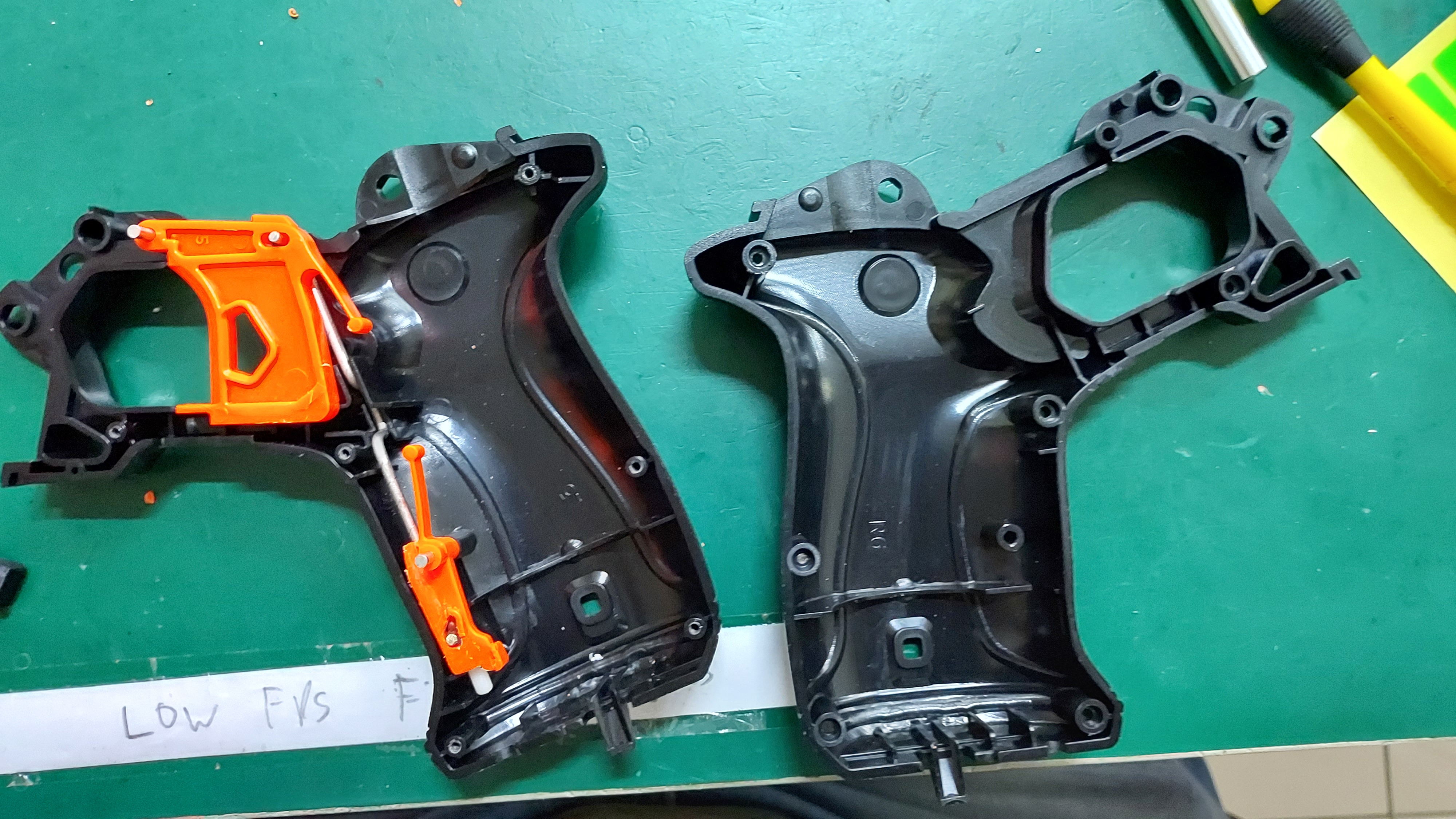
Step 1: Open up your NERF Rival Knockout unit and remove the upper receiver unit and other orange parts, except for the trigger and catch plate. There is no need to brute force the removal of the barrel primer for the knockout kit, as once you've opened the upper receiver you should be able to see the screws to remove the barrel primer to place your rival foam ball rounds in the unit.
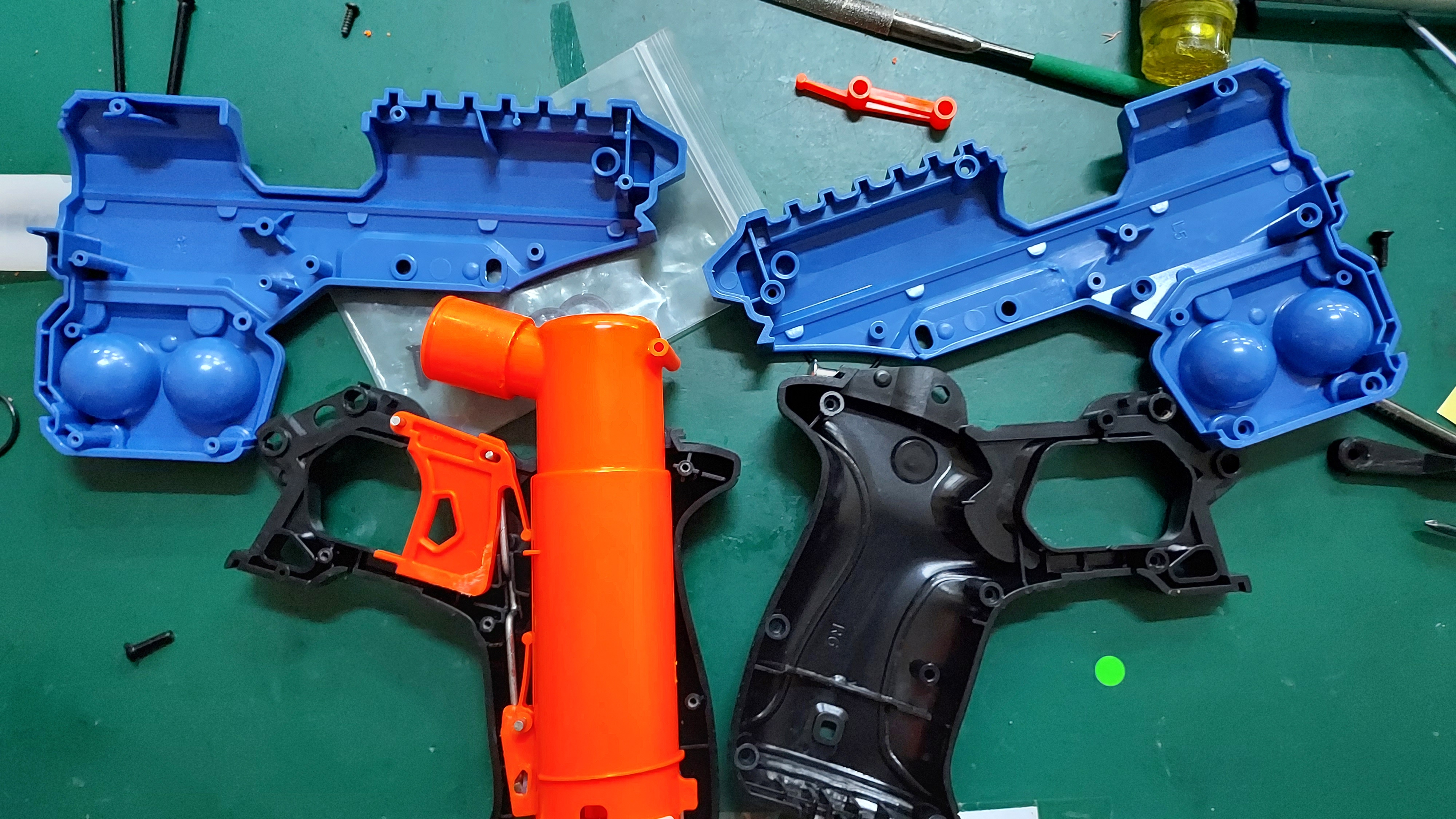
This is how it should look like after opening the blaster and removing the other orange parts of the blaster.
After removing those pieces and upper shell, place them aside into a bag/box and work on the lower grip of the knockout unit.
Step 2: Remove the air restrictor built into the plunger assembly of the knockout kit.
Usage of a dremel drill, blade and/or nipper is highly encouraged to ensure the proper removal of the air restrictor. After cutting and removing the air restrictor, you have a choice of cleaning the burrs of the removed air restrictor to make it cleaner. Do be careful not to over clean it, the plunger assembly thickness is very thin. The picture below is the closest I have managed to get it cleaned.
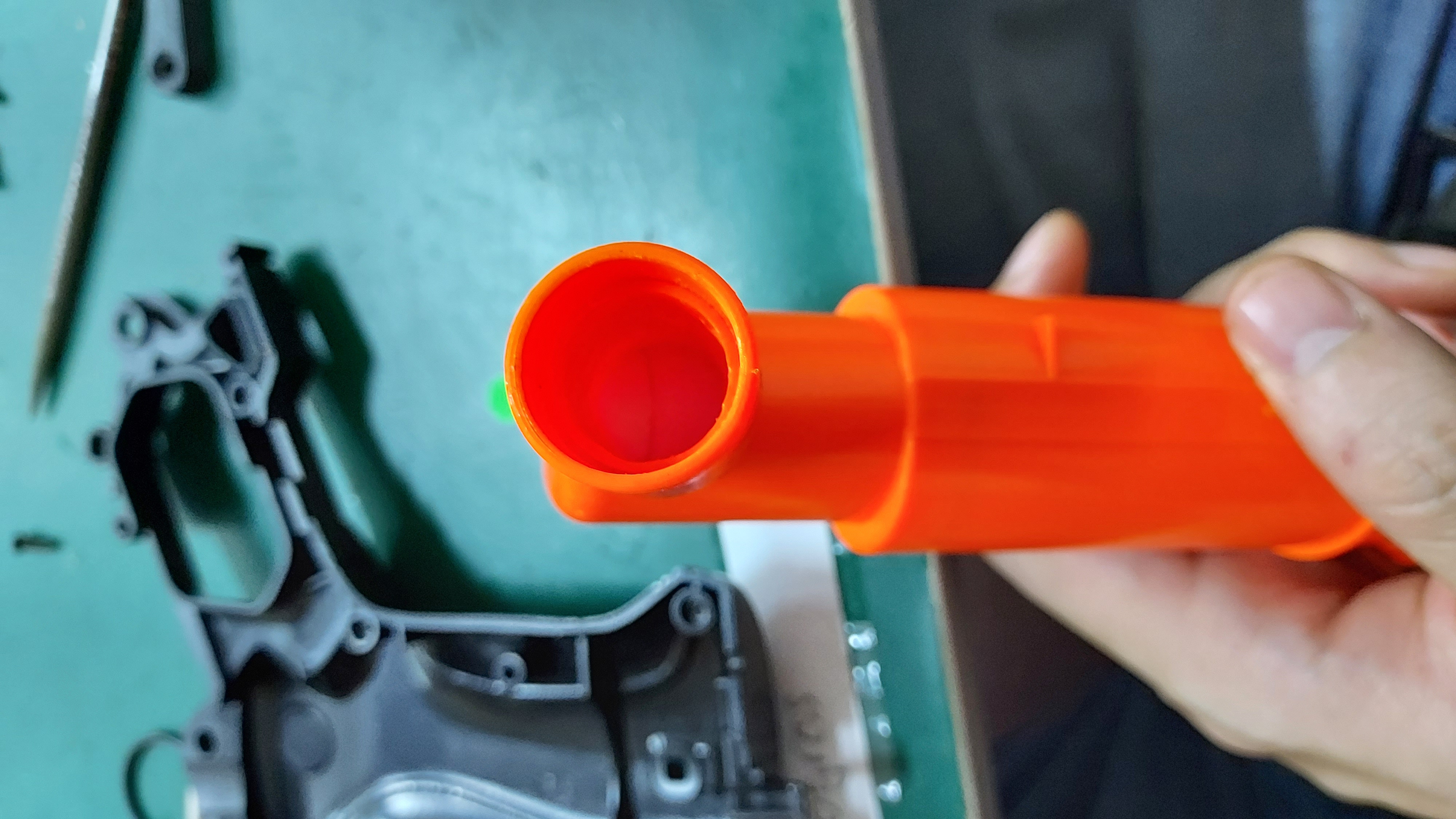
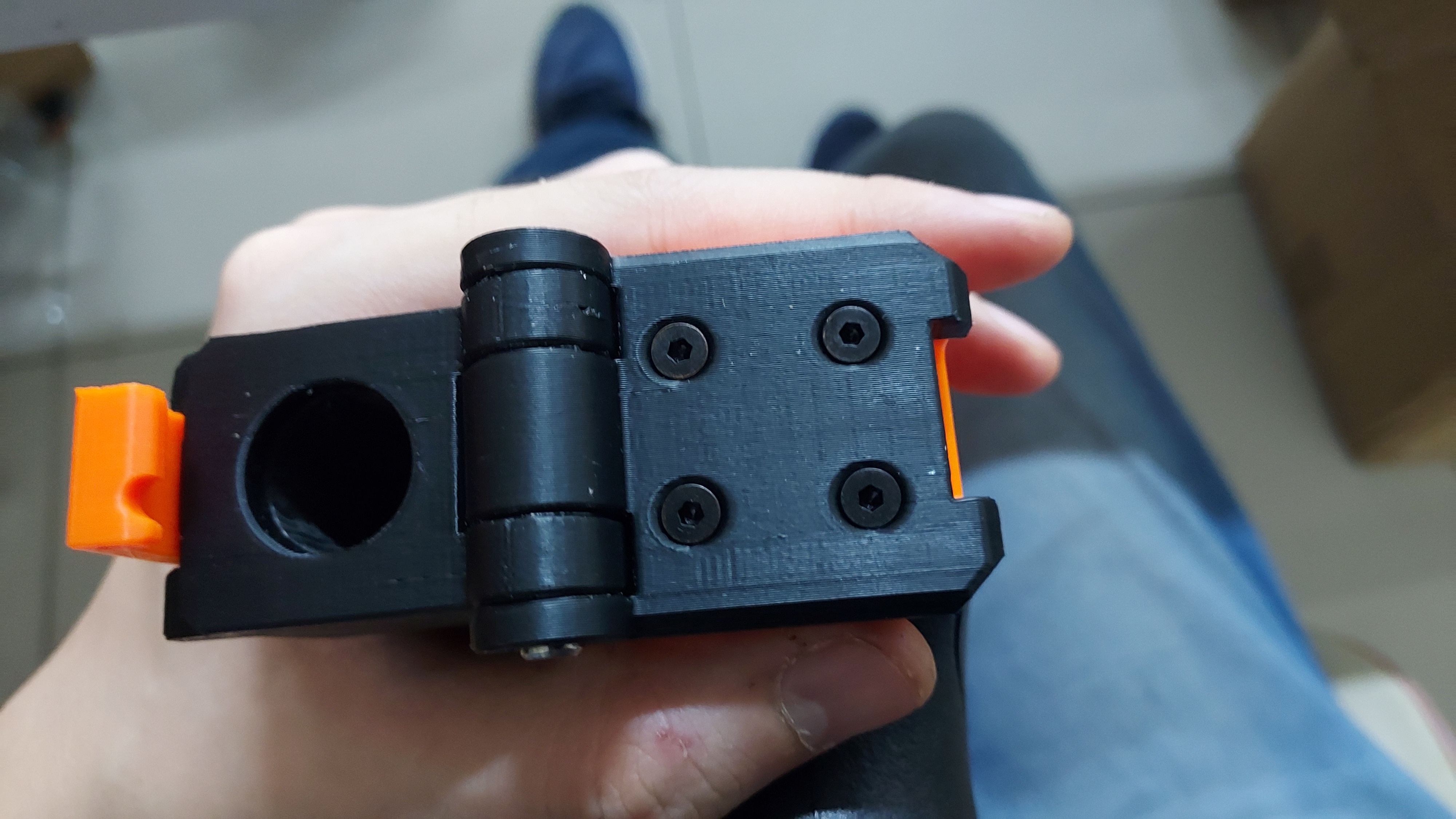
Drill a hole at the bottom of the grip for the tube to sit through, as shown in the picture below.
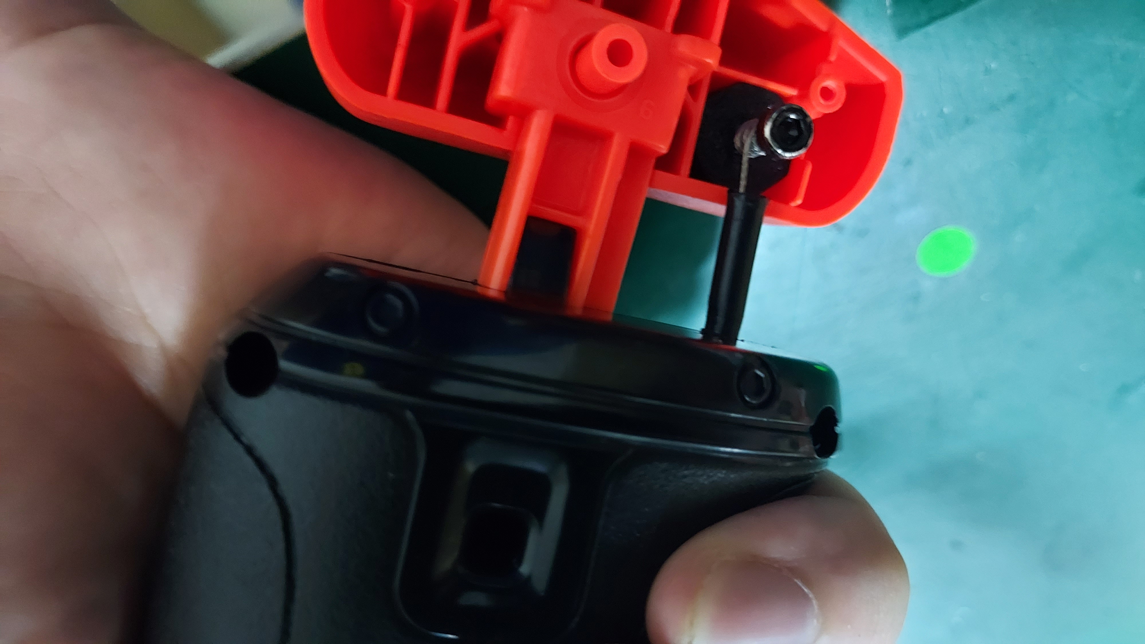
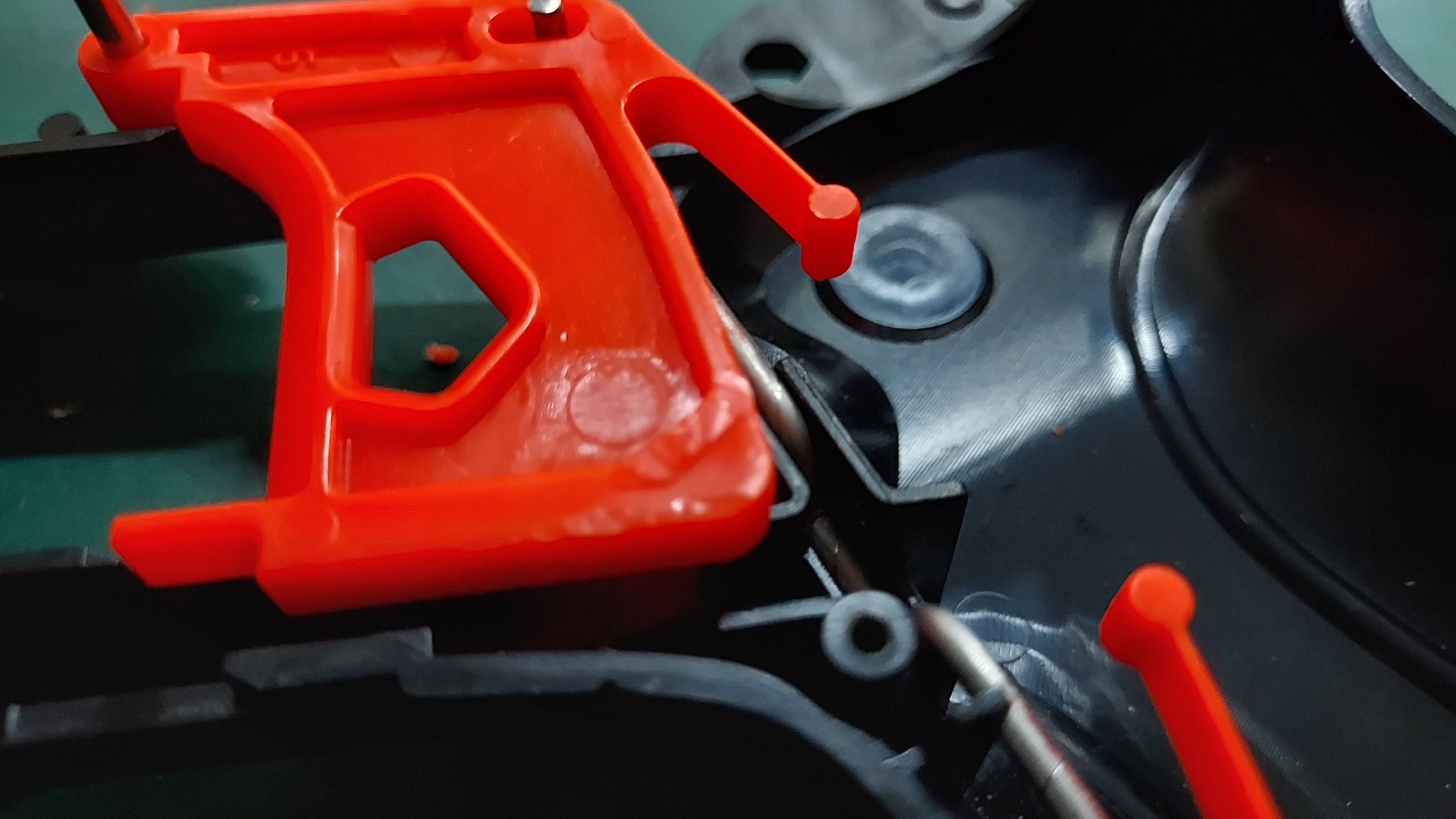
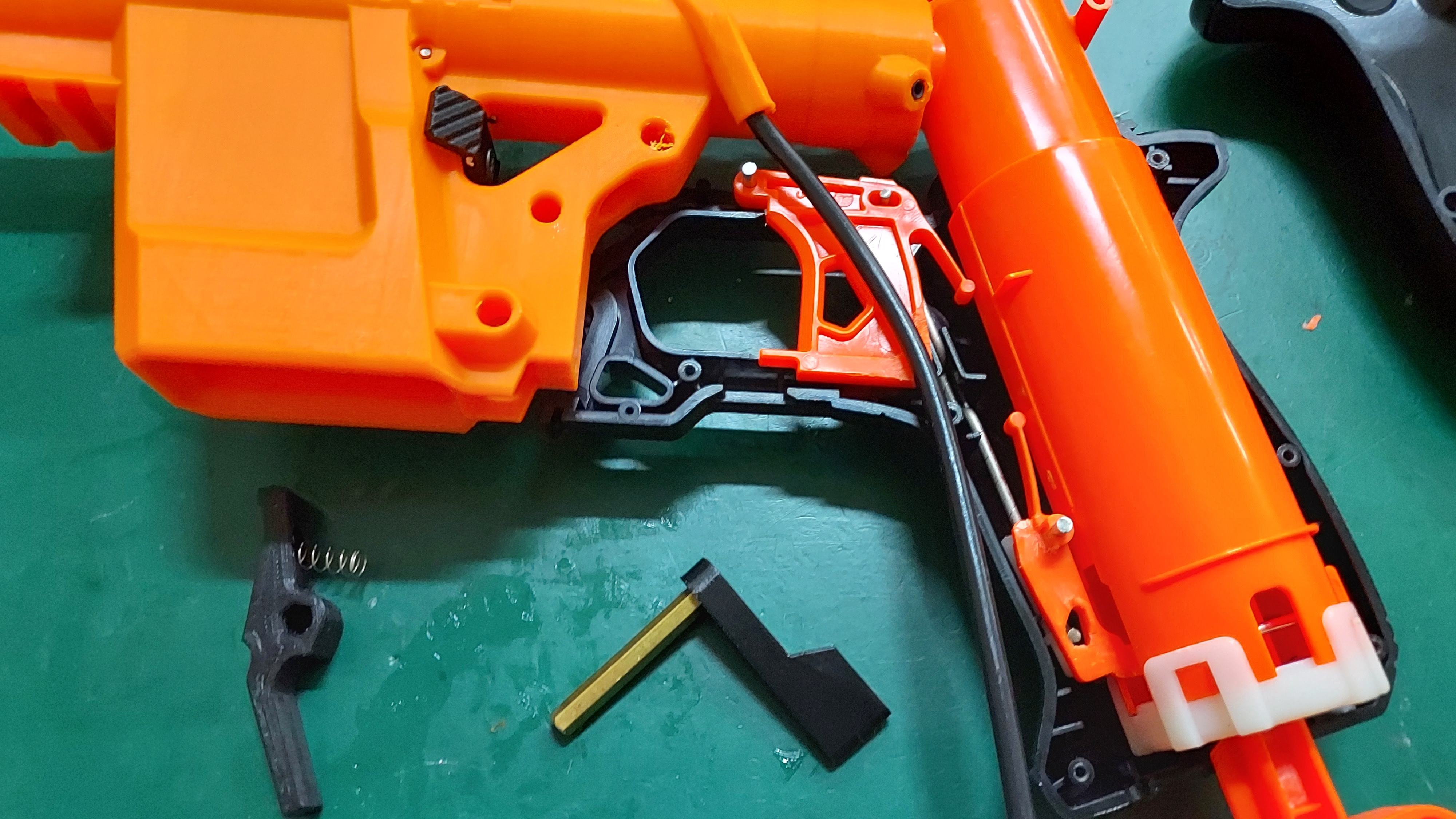
Step 3: Sand down the trigger wing and flatten a part of the catch plate.
Ensure that they are as close to the body as possible. The reason for this sanding is because there is a tube on the receiver shell of the knockout kit and ensure the smooth movements of the priming and shooting of the unit.
Trigger Wing Removal Catch Plate Flattening
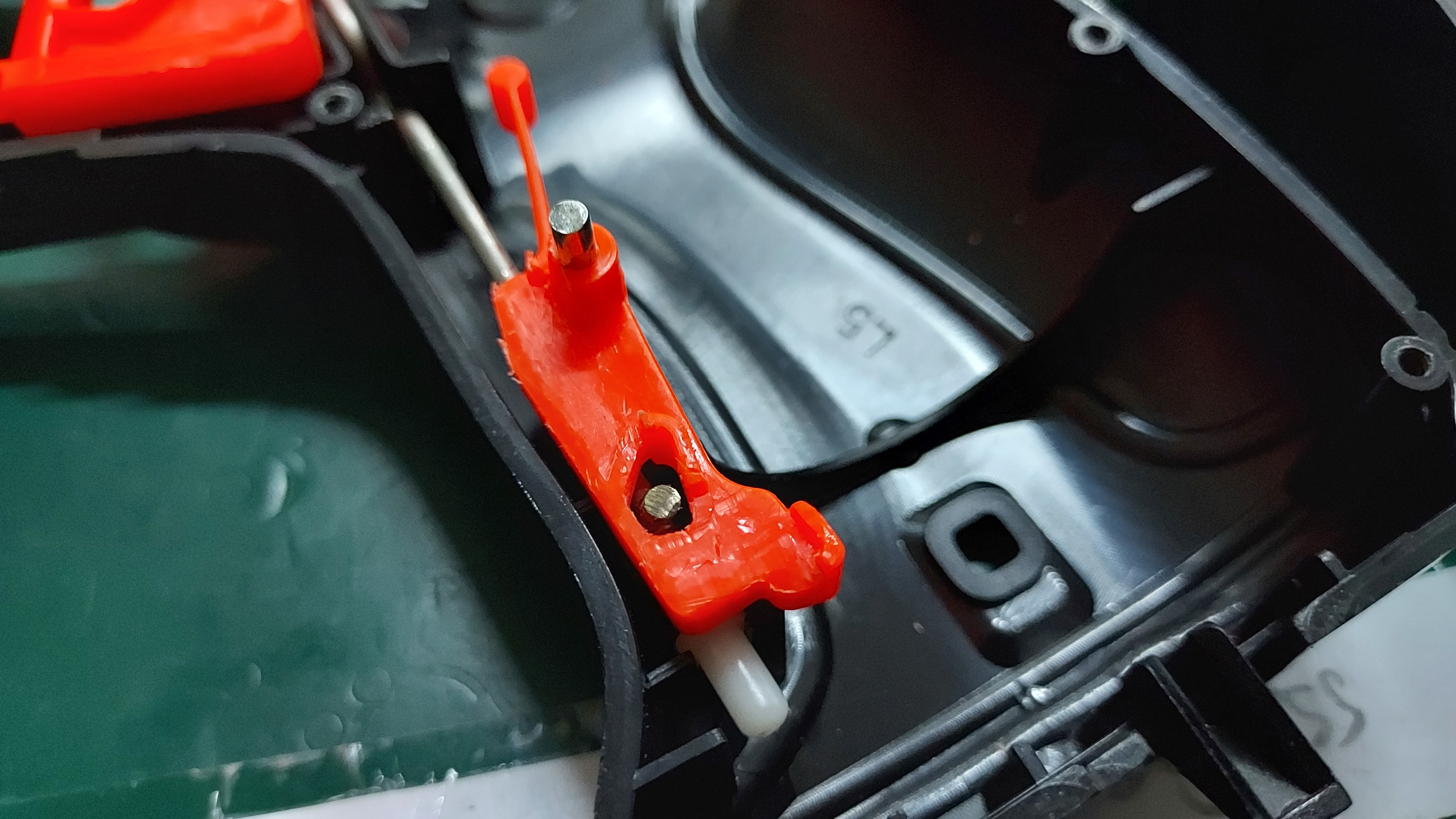
Metal Bar as close to the tallest part of the catch
Don't forget about sanding down the trigger bar of the knockout kit. Mainly, the part of the trigger bar that is on the catch plate, because it needs to be flush with the tall part of the catch plate and prevent itself from sliding inside the grip piece. Another part to note is the primer block at the bottom of the grip.
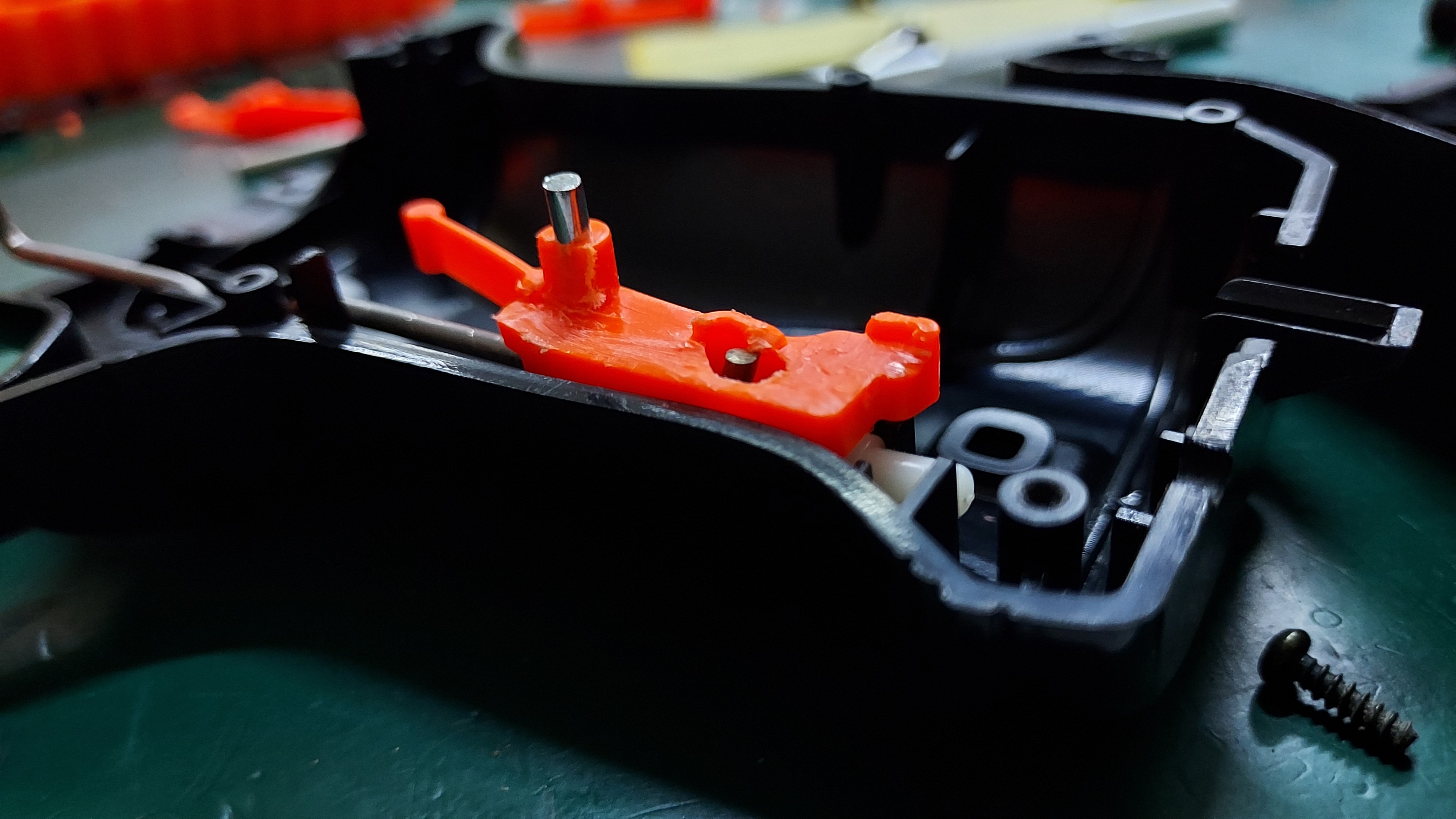
The bar will have a small nub to ensure that the primer is held once pushed back in place. Do remove the nubs on both sides to ensure smooth priming for this kit.
 Removed holder nub of the primer block
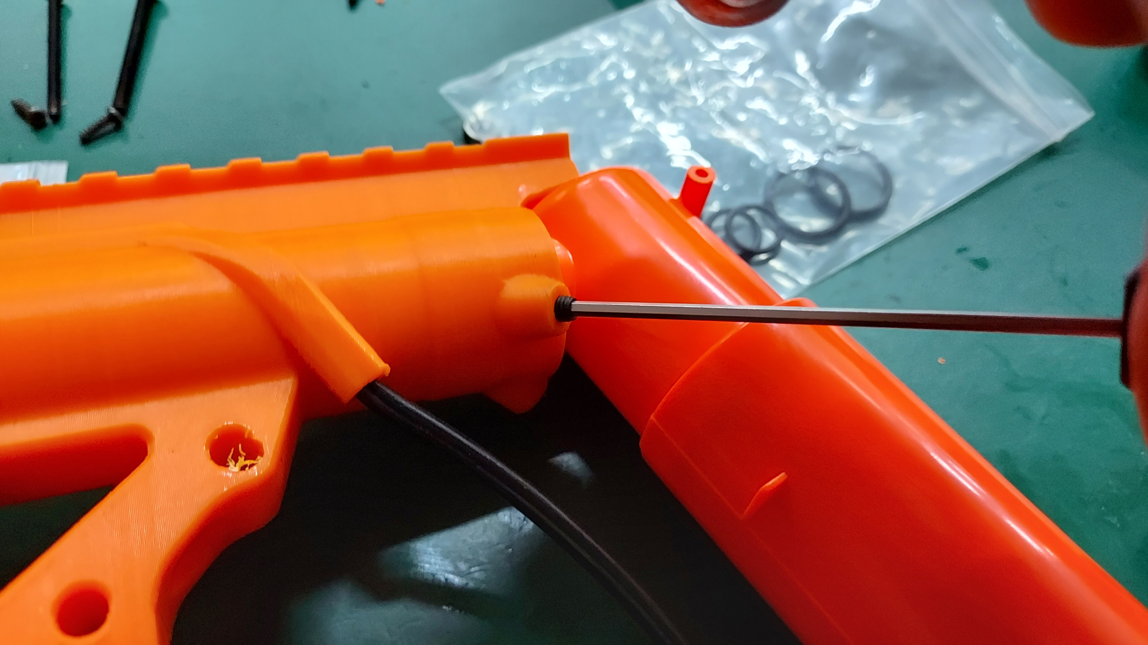
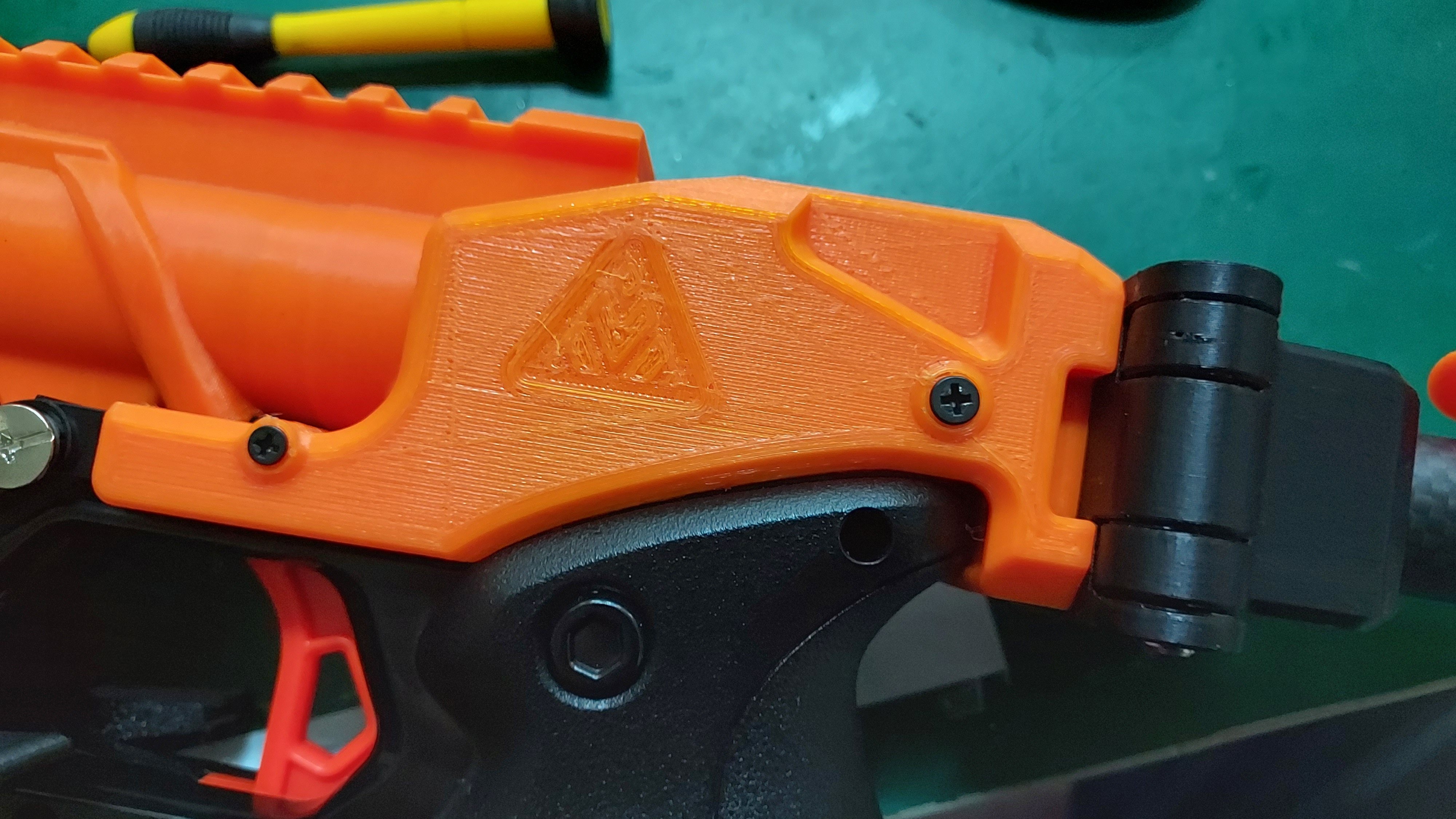
Step 4: Install the receiver piece to the plunger tube assembly. Do be careful when installing the receiver piece to the plunger tube assembly as it could kill the o-ring built together with the Knockout blaster. Lubricate the o-ring piece to ensure that it slides in properly and ensures the o-ring is not cut halfway installing.
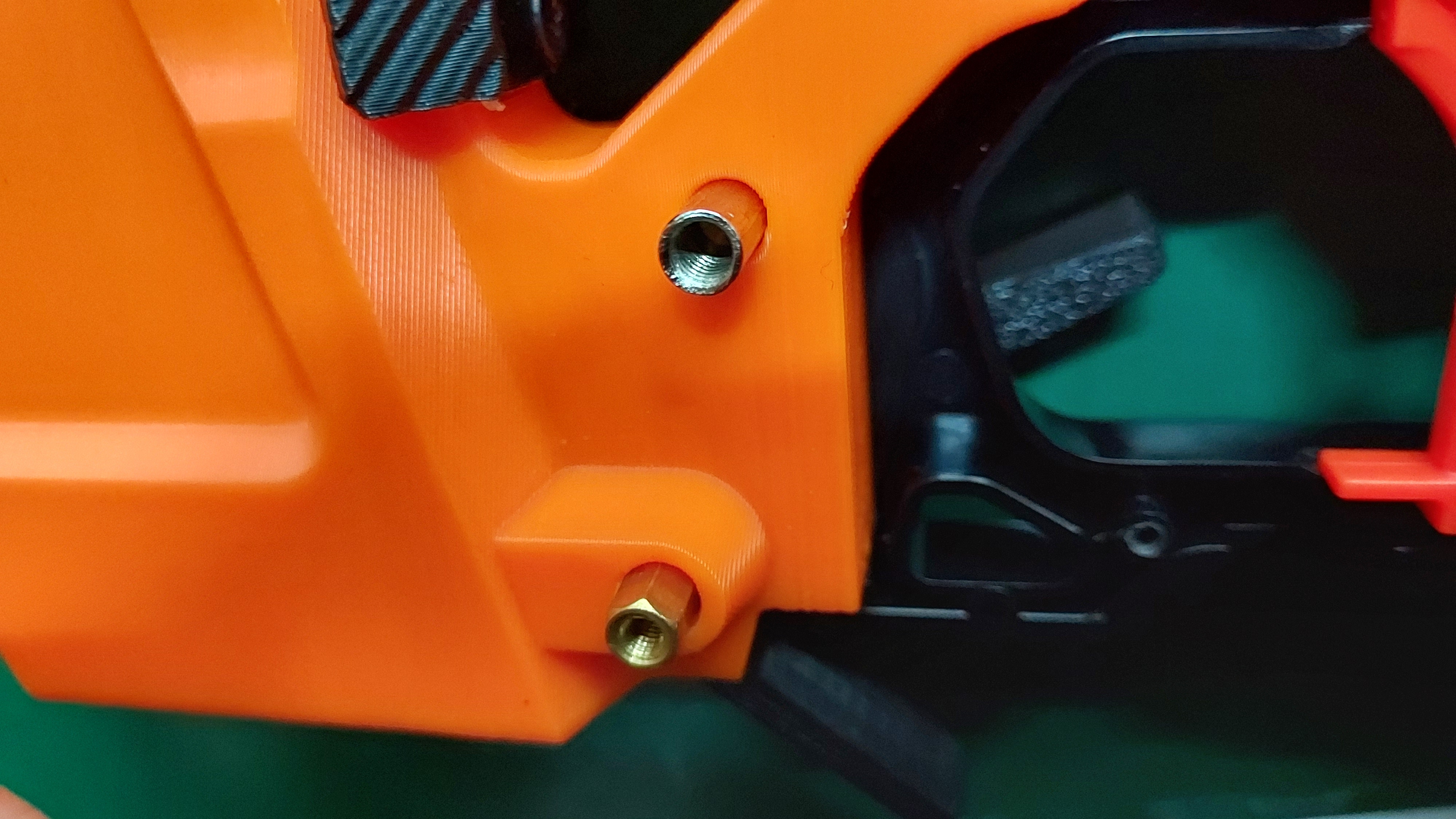
After placing it in, tighten 3 grub screws at the receiver shell to ensure that the plunger tube assembly is secured properly into the receiver shell.
 Screw 1
 - screw 2.jpg) Screw 2
Screw 2
 - screw 3.jpg) Screw 3
Screw 3
Alternatively if the o-ring is cut during installation, as shown in the picture below.
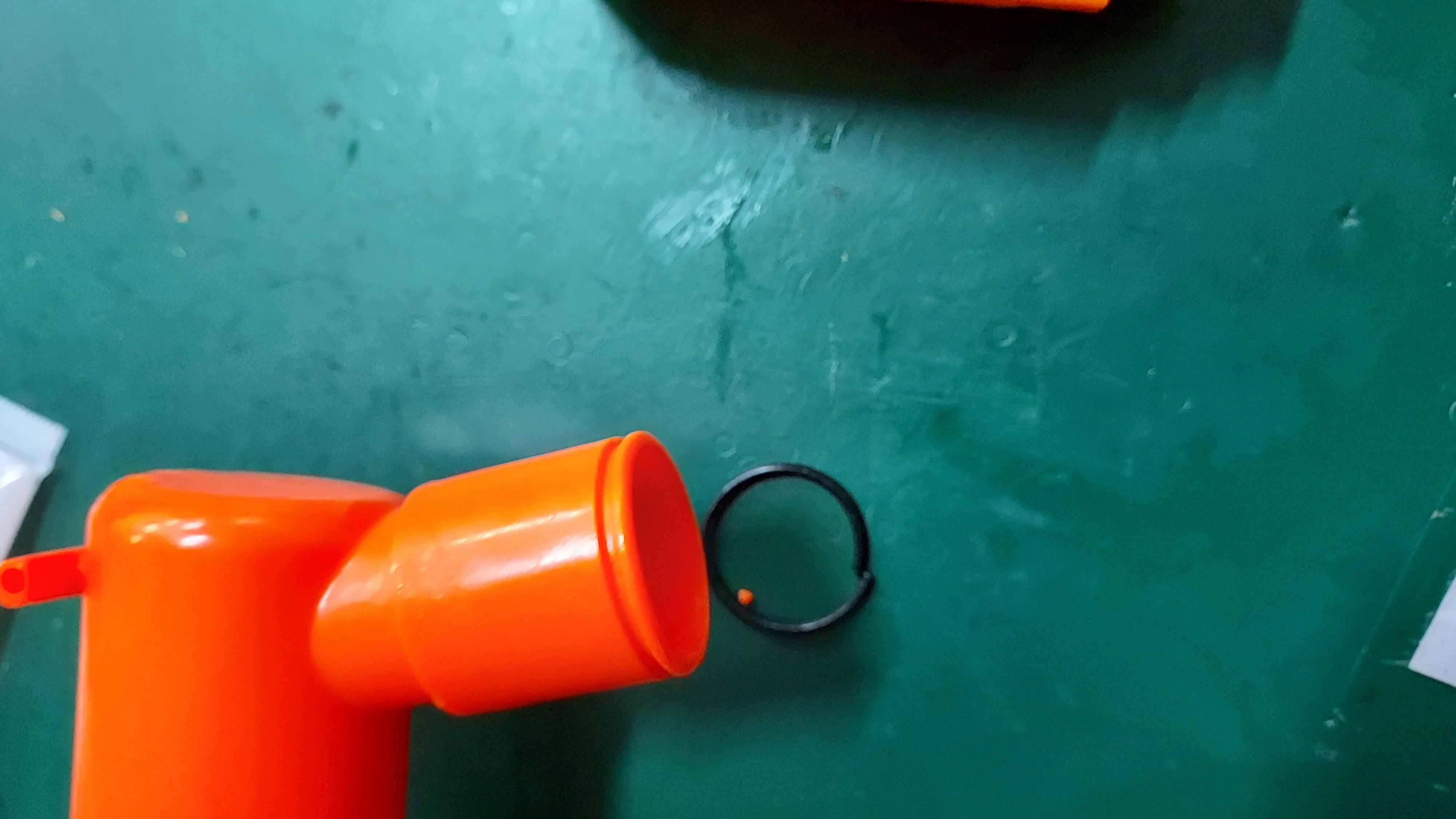 Destroyed original o-ring
Do use the slightly larger o-ring to aid in this build, by placing it inside the groove, as shown in the picture below, and tighten the screws from there with the plunger tube assembly placed together. NOTE if the entry for the plunger tube is too tight, do sand it to make it a bit larger for easier entry.
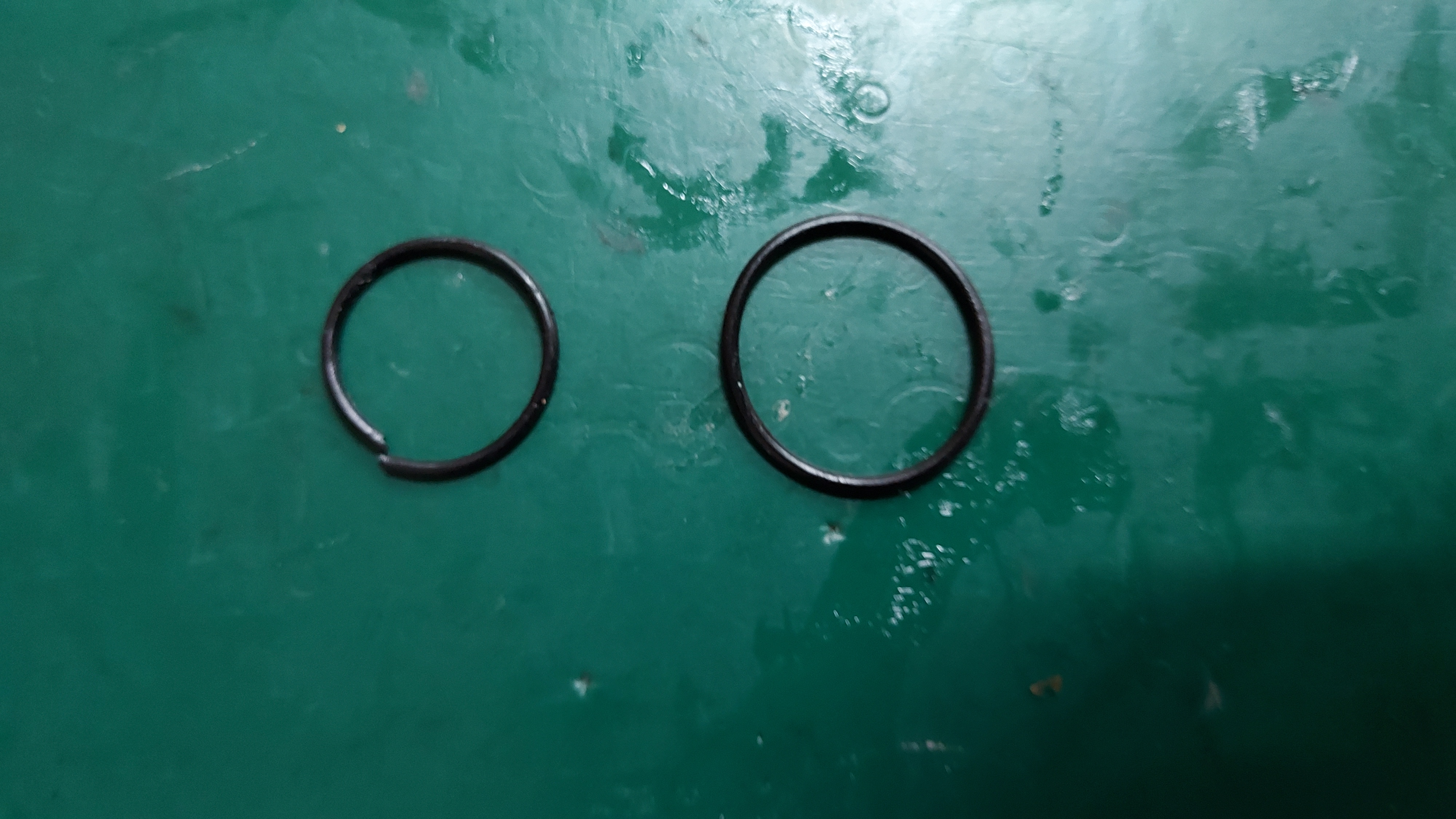
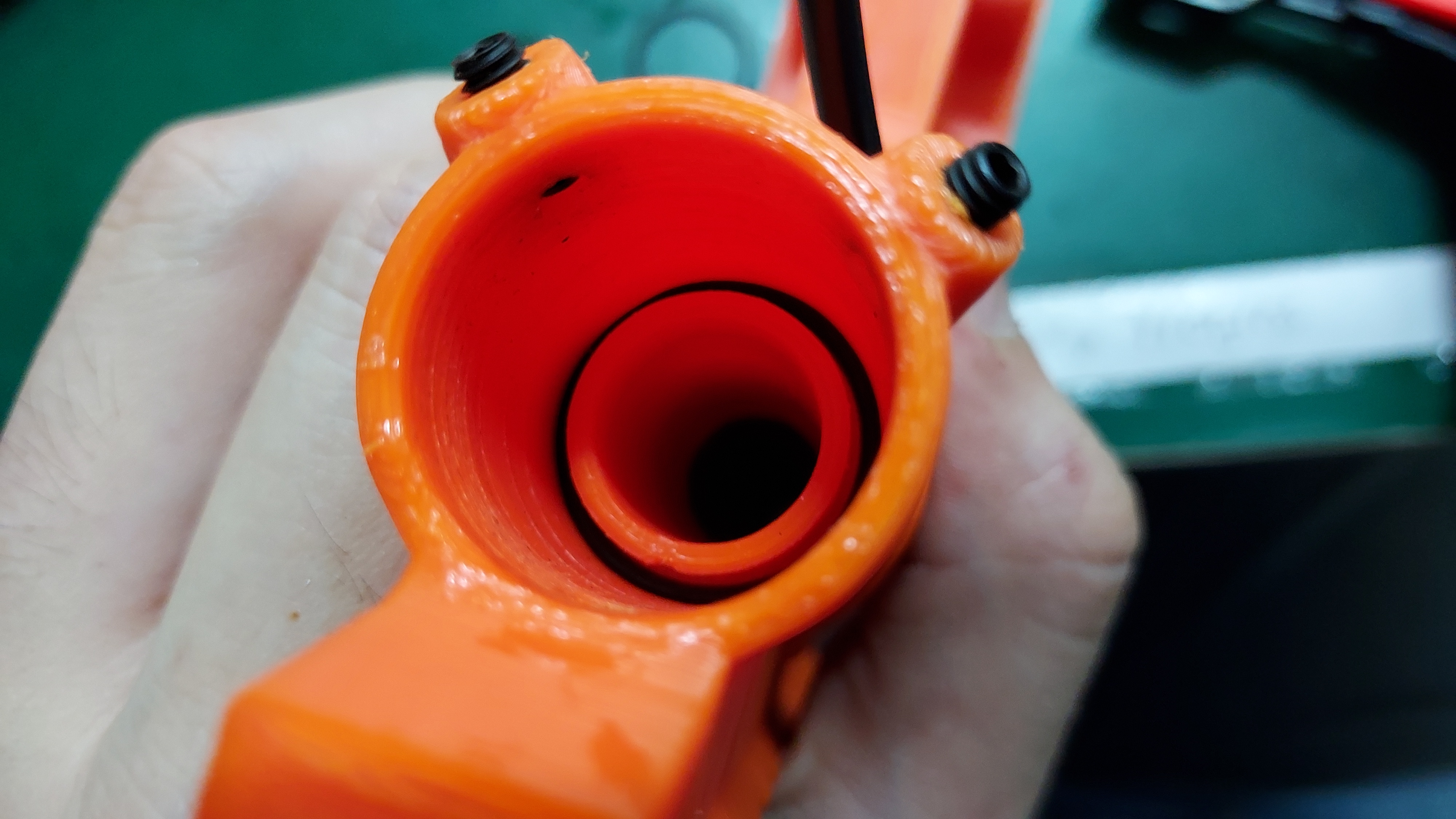
O-ring size difference Inserted O-ring
Step 5: Lower grip installation
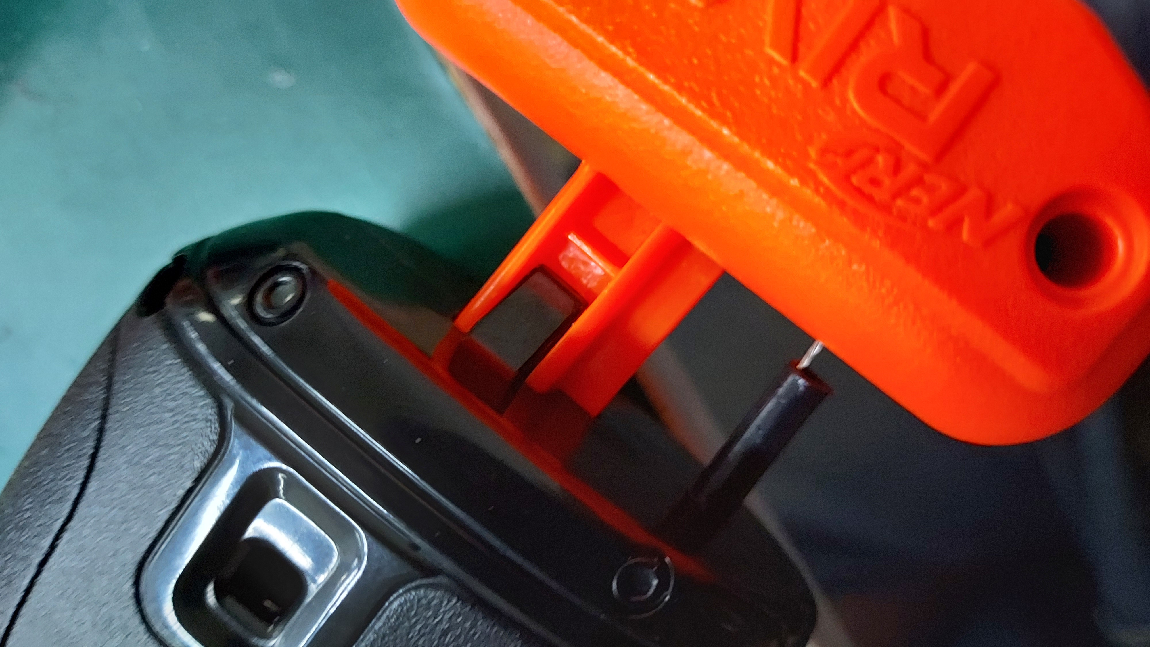
When installing the lower grip piece for the Knockout, remove one side of the extended mag release to ease the installation process as shown in picture 1 below.
Picture 1 Picture 2
If the mag release combo came off from the receiver hold, as shown in picture 2 above, the installation can still be done properly. Just ensure that if the pieces come off, they land inside the box for easy recovery.
Use one of the receiver holding pins to ensure that the lower grip piece doesn't come off easily, as shown in the picture below.
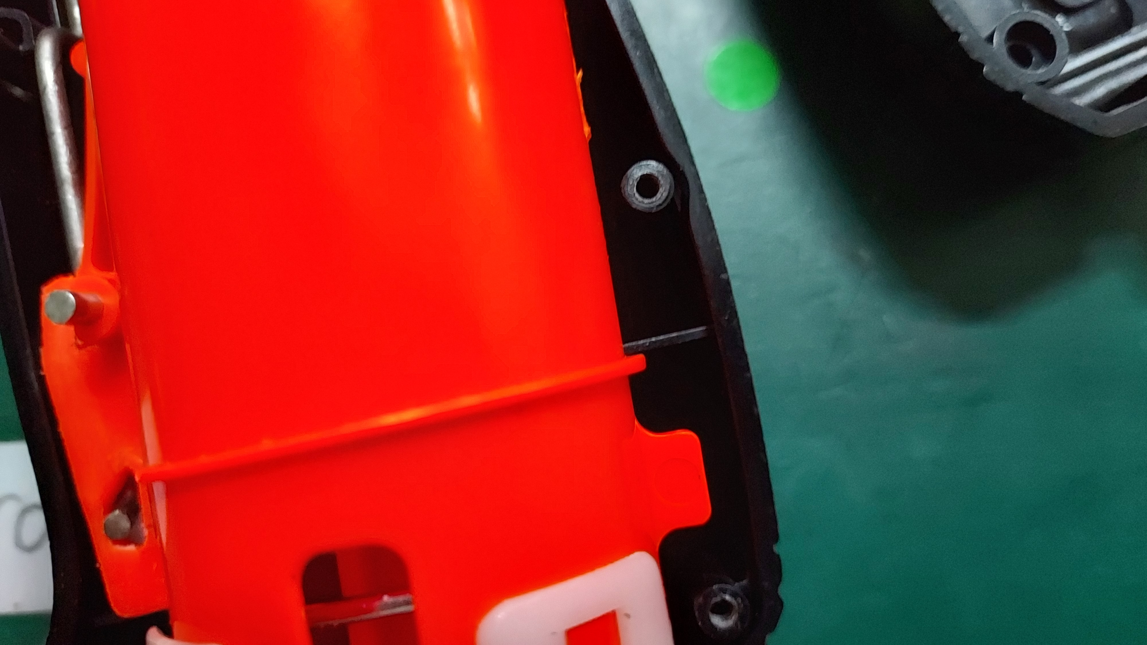
Be sure that the plunger tube assembly is placed properly inside the lower grip, following this marker as shown in the picture below.
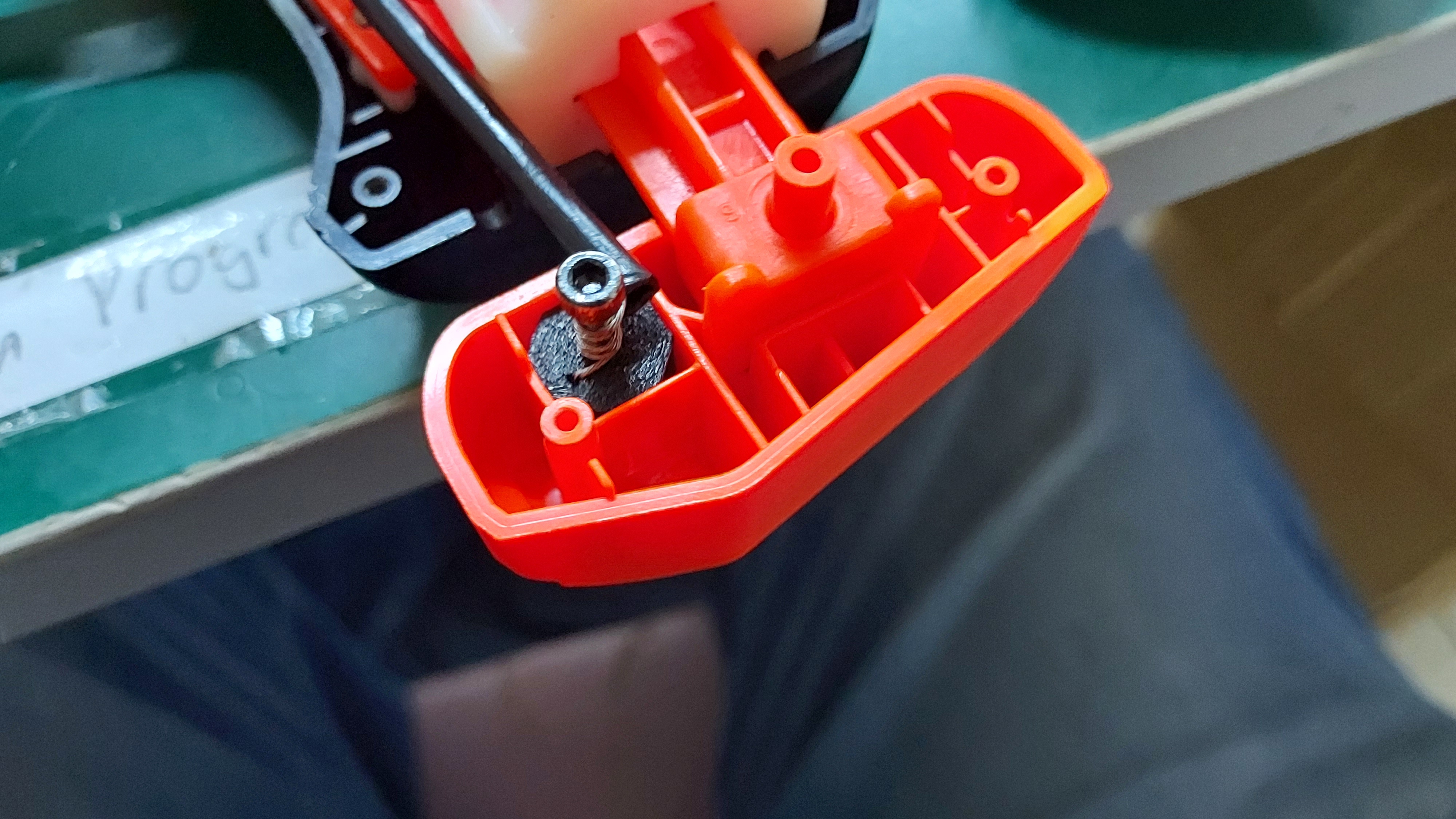
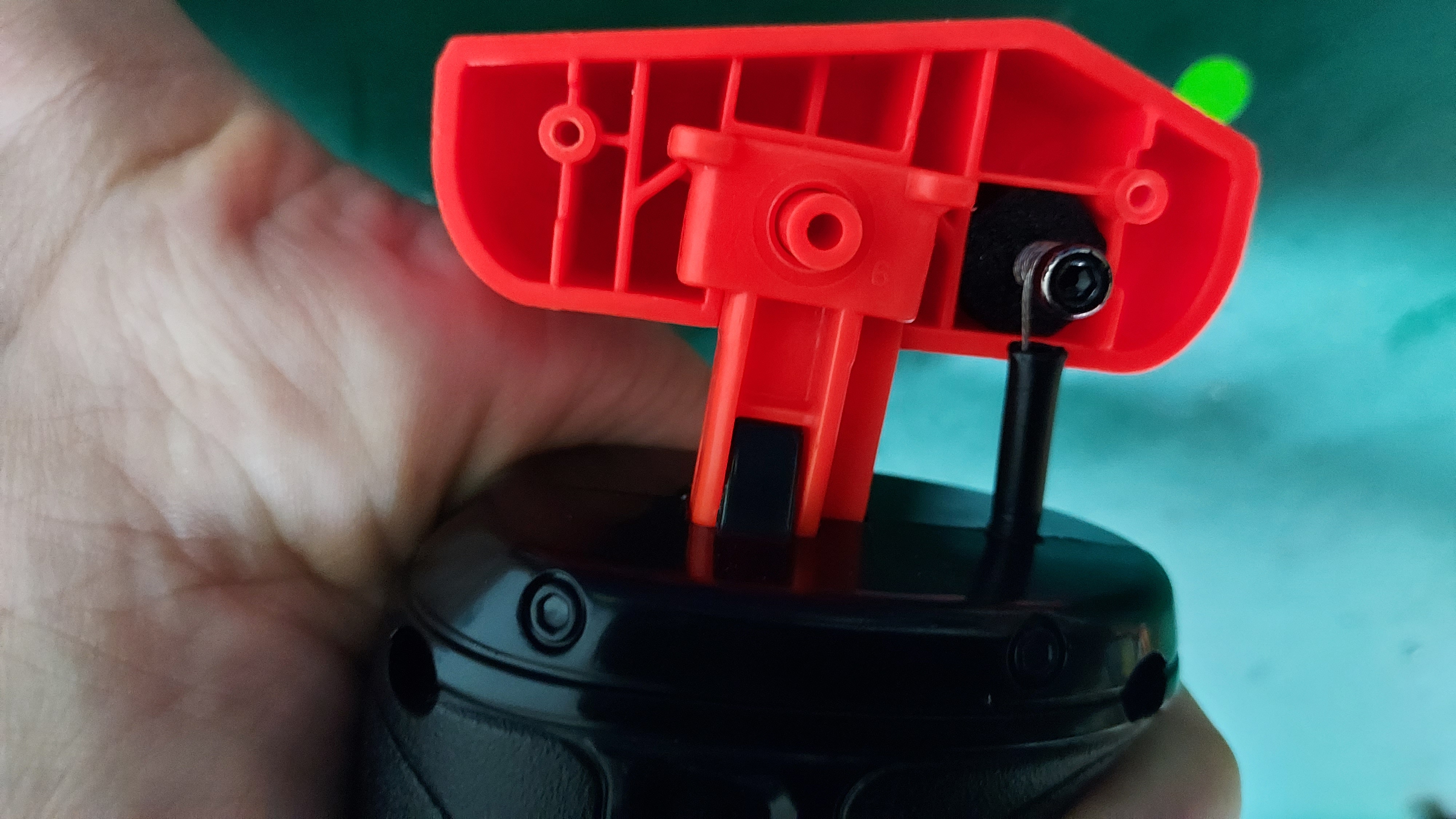
Having one side of the priming block set at the priming line, tighten the wire at the anchor point screw and place it at the top cut out for the primer block. If there is no place for the block to hold, place as much foam padding to ensure the anchor doesn't move about in the primer.
Step 6: Closing the grip & Primer block
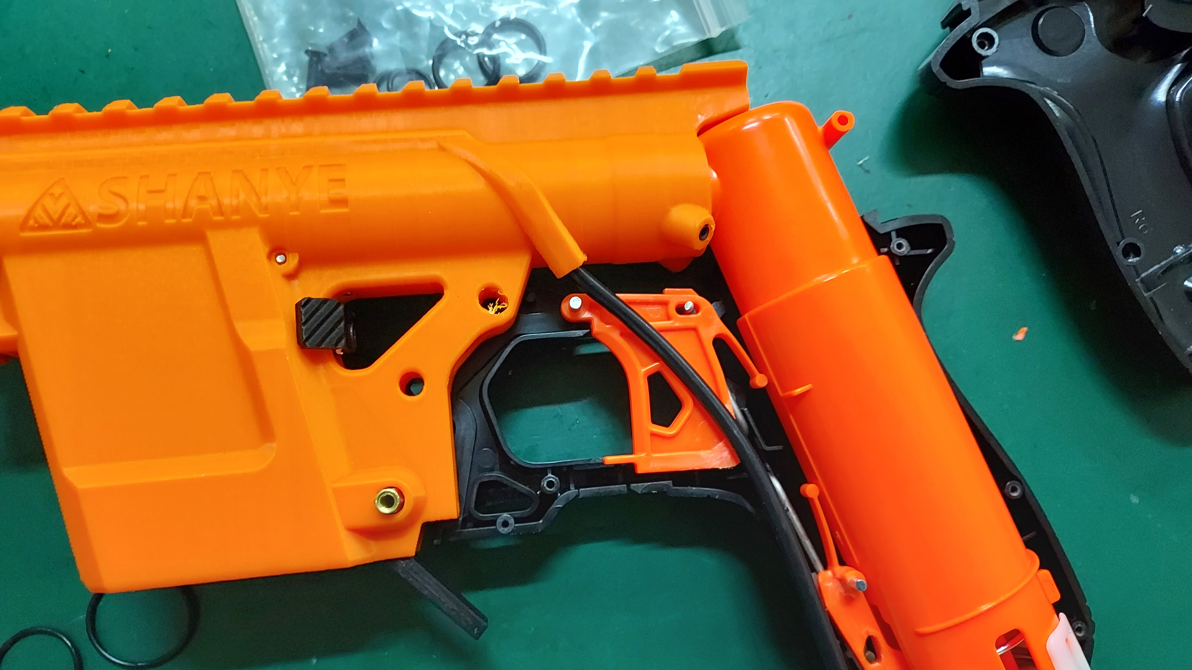
Before closing the grip, check the wire tube is place on the correct position, based on the picture below.
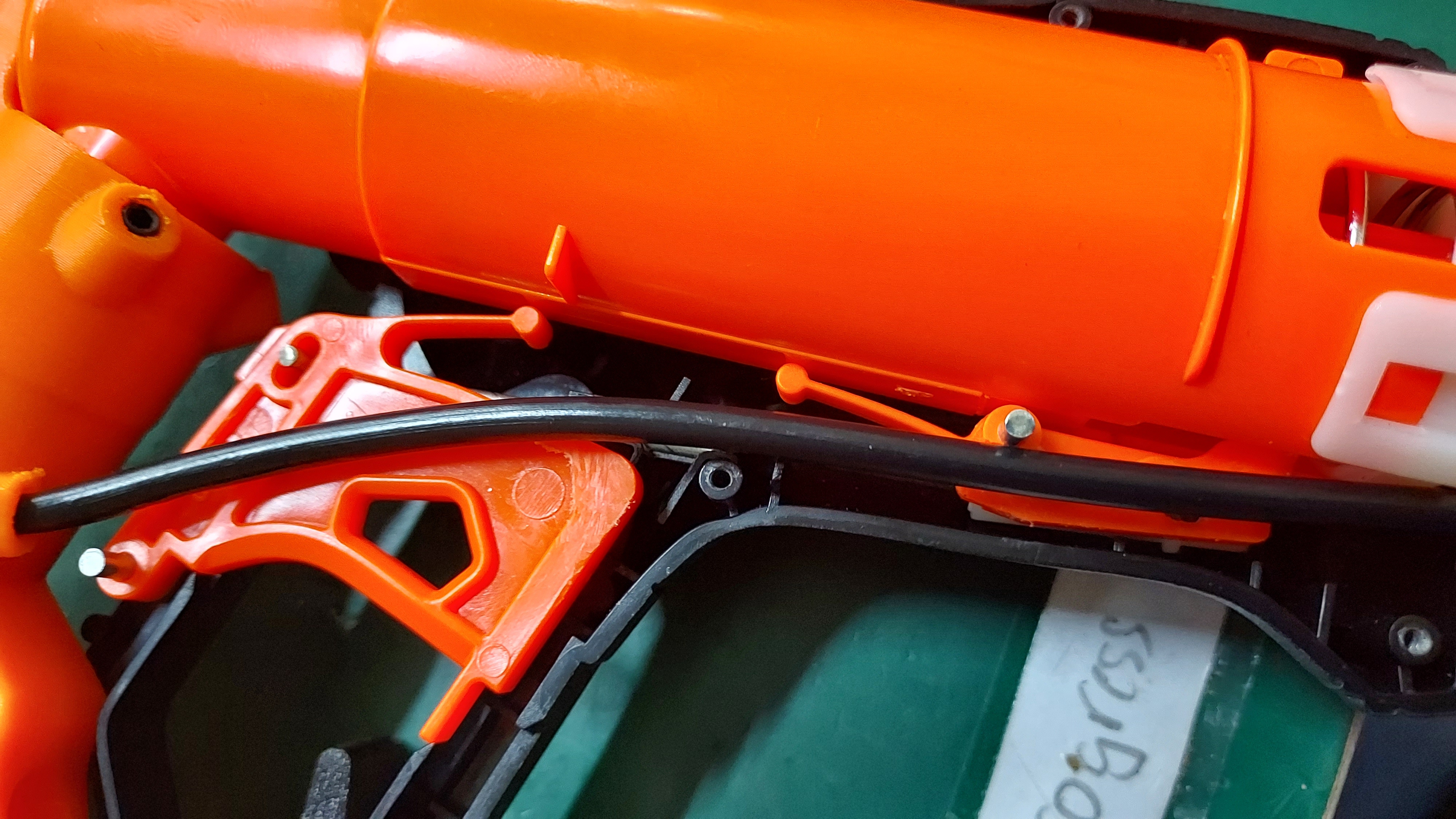
To close the grip , place the other side of the grip shell by holding it at the rear part of the grip, as shown in the picture below.
As you try to close the grip, the wire tubing will prevent it from closing completely. You have to push/adjust the tubing by using either a flathead screw driver or a hex head screwdriver so that the grip can close properly.
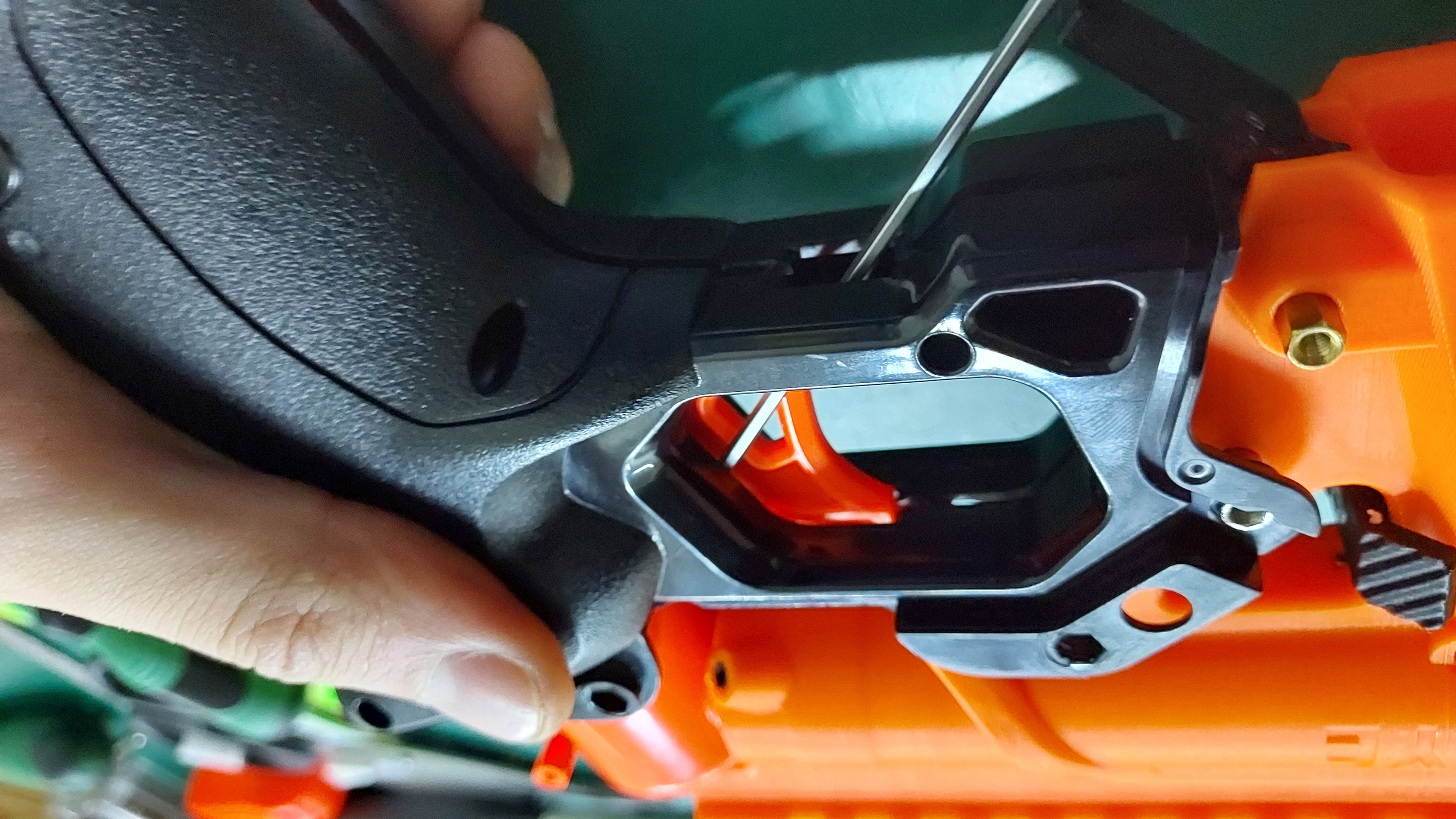
Once the grip is closed on the tubing part, look down at the priming part of the blaster. If bar is inside the grip piece, pull it down slightly in order to complete the closure of the grip and place the primer bar in the original position, as shown in the picture below
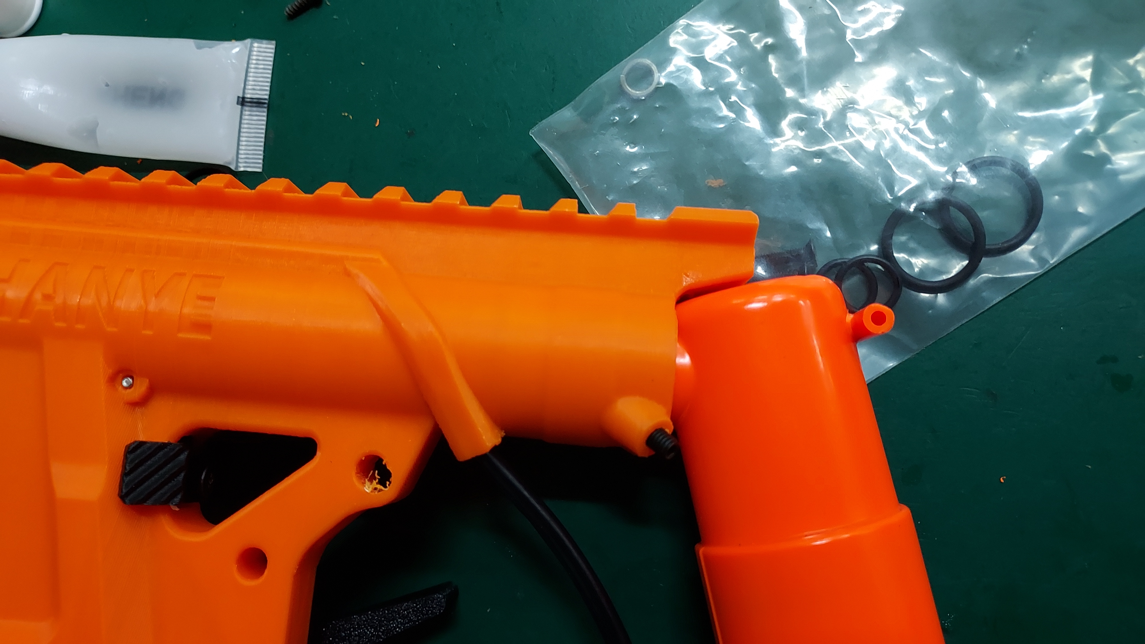
Before closing the primer block, do trim the rubber tubing that protects the wire.
Optionally, you can cut the extra tubing at the bottom of the grip to make it look neater.
.jpg)
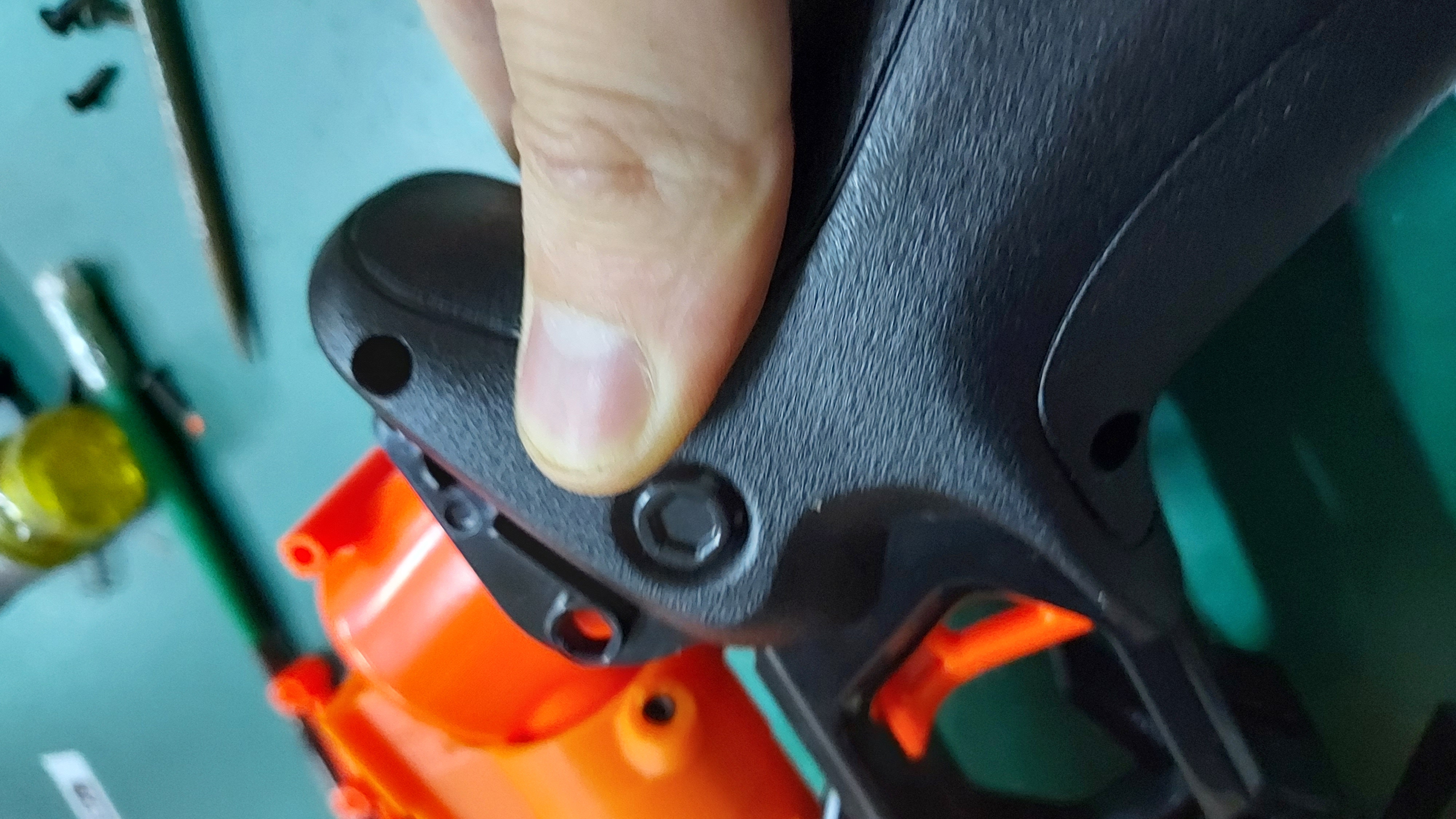
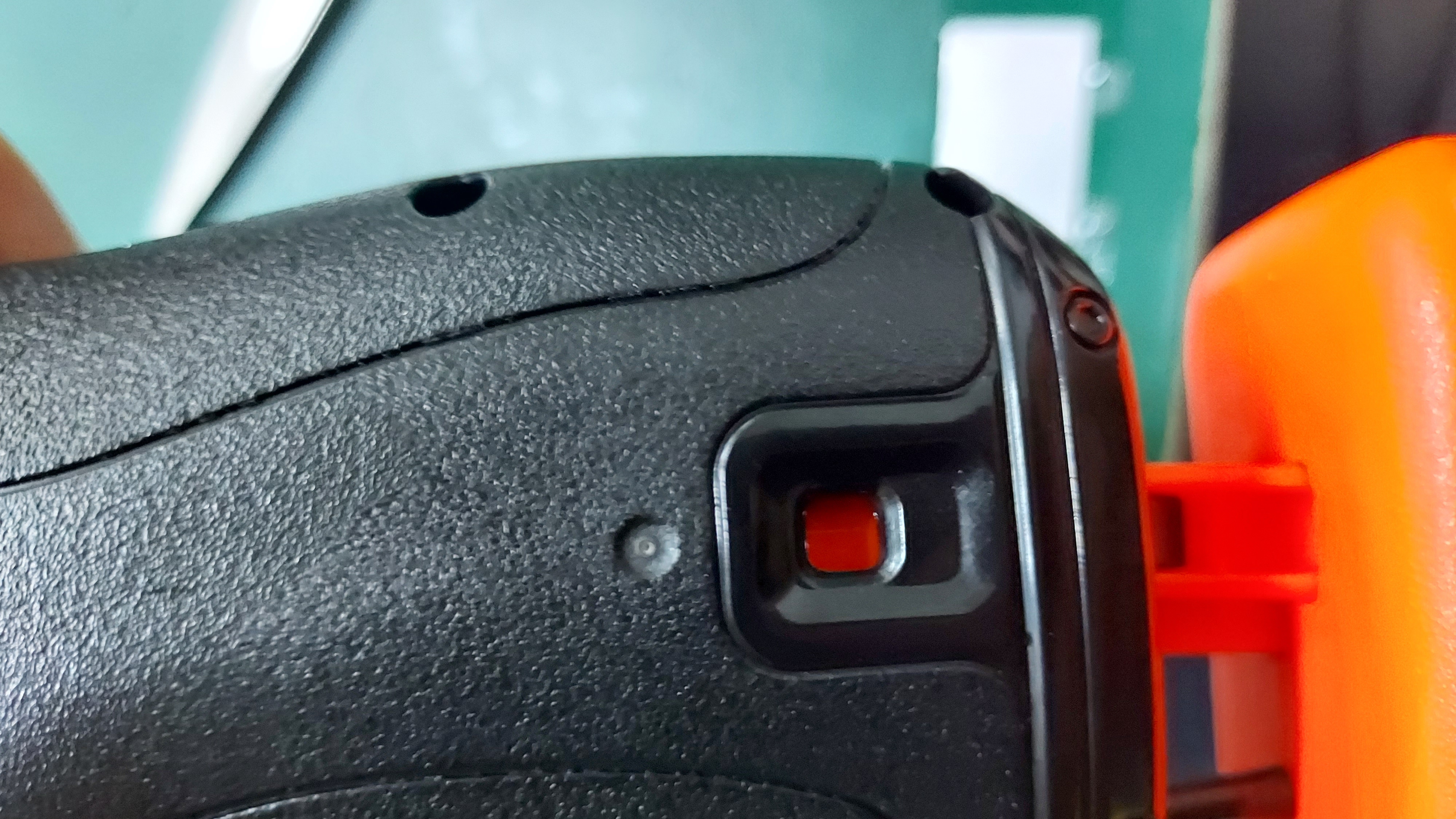
Now that the grip is closed, secure it with the screws and test if the piston from the plunger tube assembly can catch. Looking at the small hole cut-out at the grip, there should be a orange indicator showing that it is primed. If it does not show the orange indicator, you will have to repeat step 3 of the catch plate sanding and/or trigger bar sanding for proper piston catching.
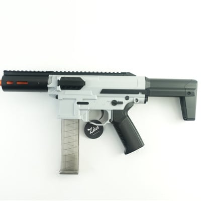
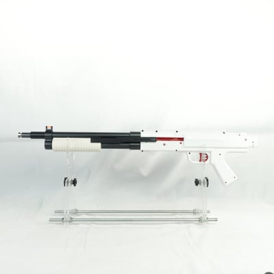
Step 7: Completing the blaster.
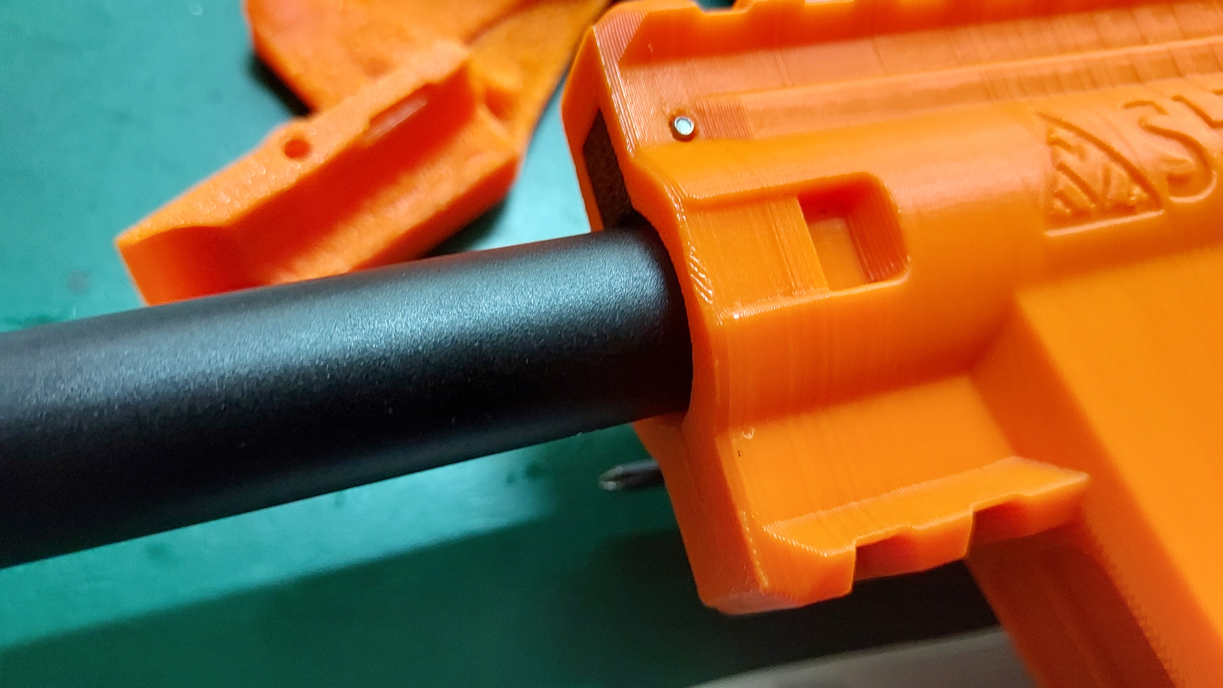
To place the handguard, do loosen the screw that holds the barrel to place it in the receiver piece. Once the barrel is in place, complete it with the handguard. If insertion for the barrel is tight for you, do sand the receiver barrel entry point for smoother insertion. If you wish to have a quick change to the barrel and handguard length, sanding the barrel entry point is HIGHLY RECOMMENDED.
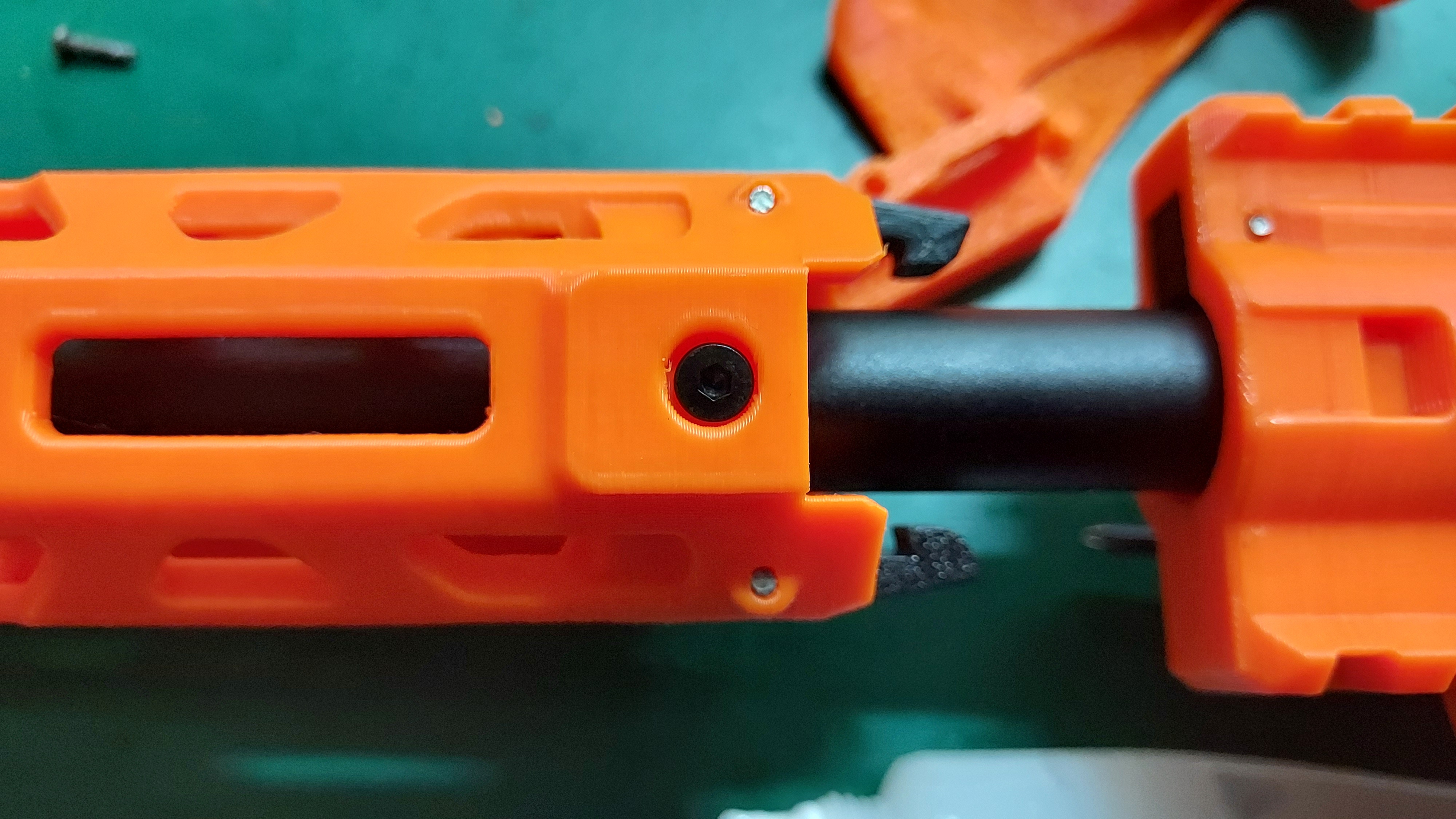
Screw in the body piece and the buttstock in place
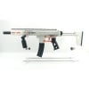
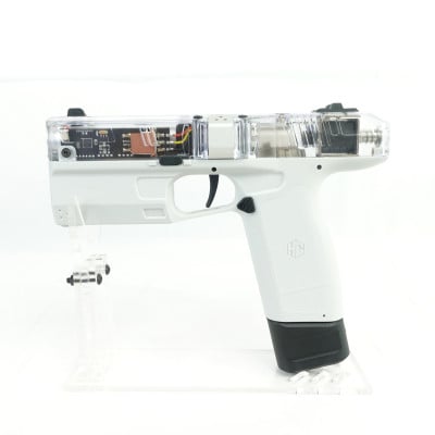
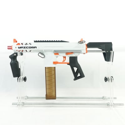
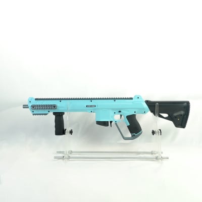
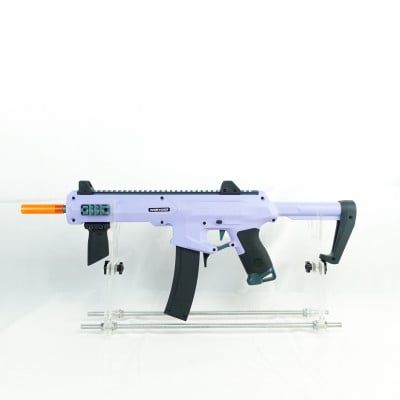
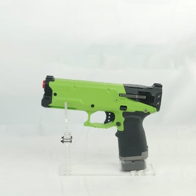
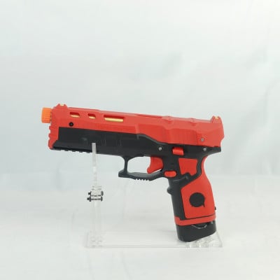
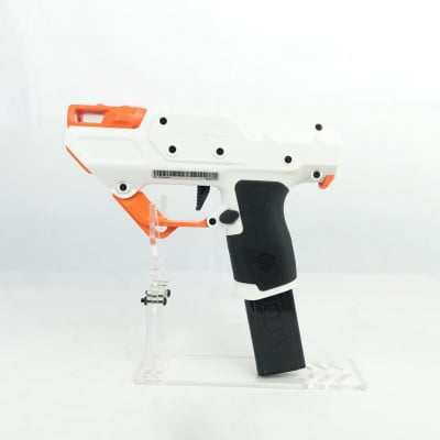
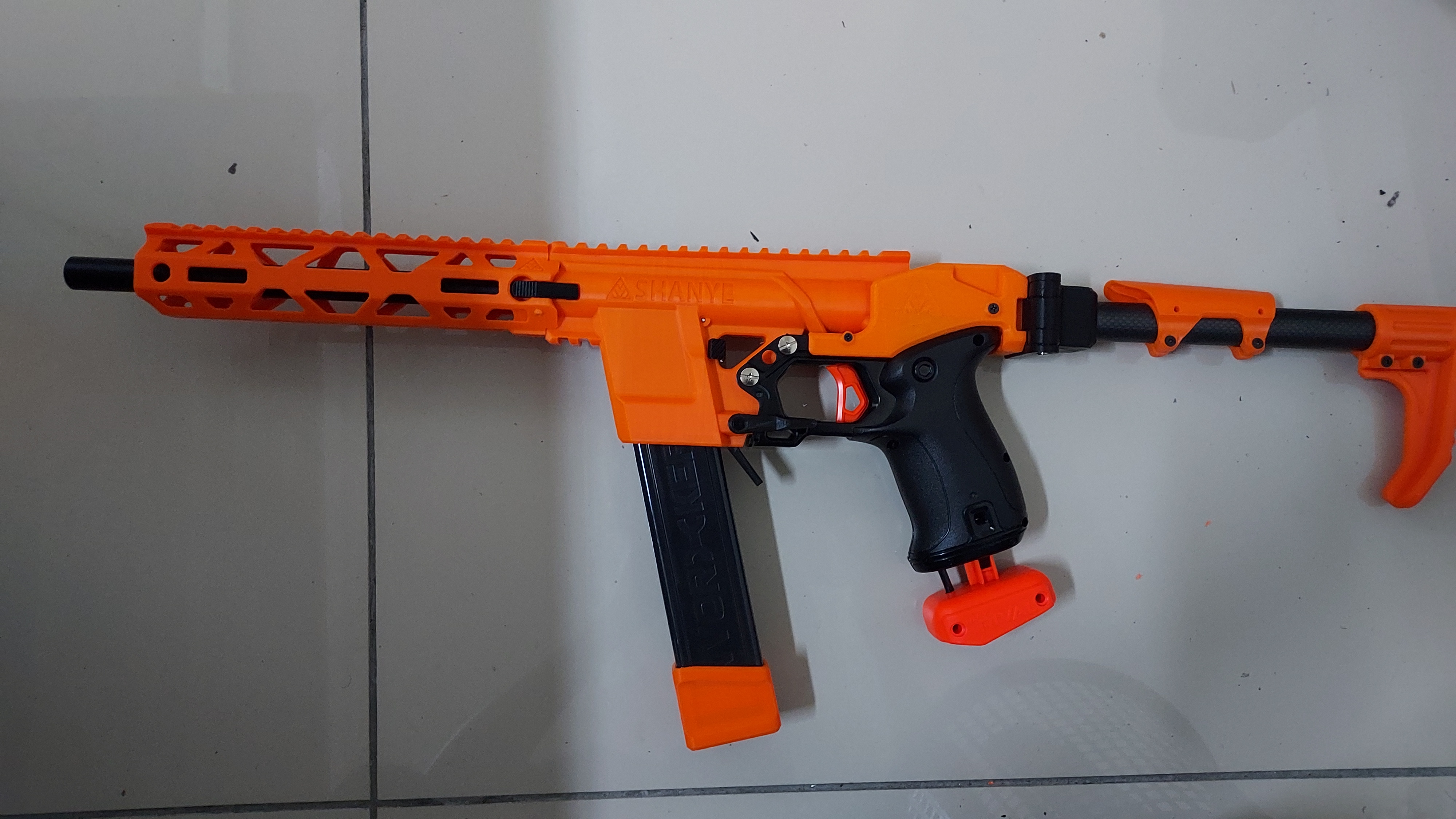
By following these steps properly, you should be having a blaster that looks like the picture at the bottom. For the mag follower and mag base provided with the kit, use the nightingale magazine and replace the original mag base with the given mag base and mag follower. You can reuse the original mag follower spring with the new magazine follower.
Leave a Comment