


Hi there modders,
Today we'll be redoing our assembly guide for the Monkee Mods Firefly Blaster V2.5. It has a long time coming that this assembly guide needs an overhaul.
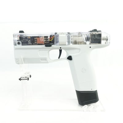
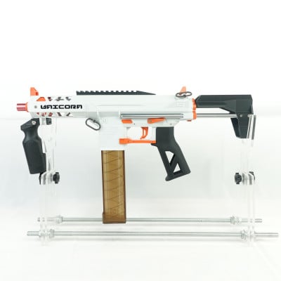
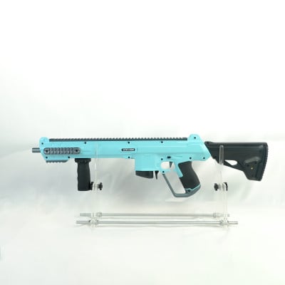
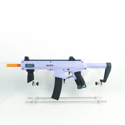
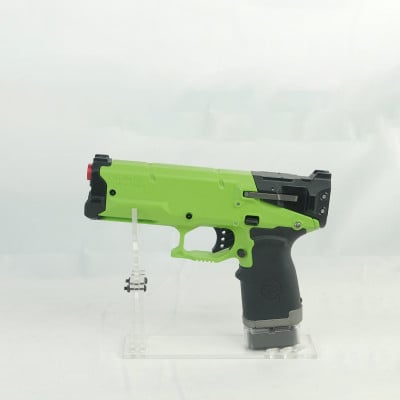
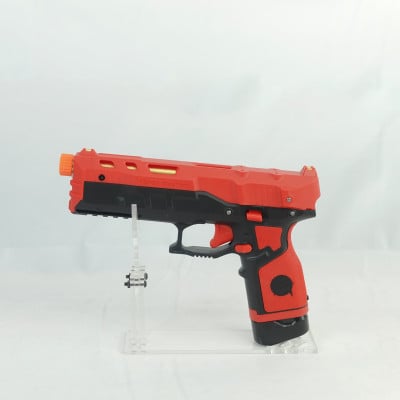
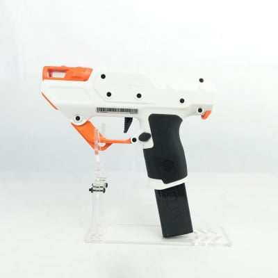
We will show you the step-by-step guide on how to build the Firefly blaster properly. We will use the White receiver shell Firefly as our base. This guide can also be used on the Yellow, Orange Transparent, and Blue Grey version of the firefly, as well as the limited time transparent firefly version, and American Foam firefly version. This guide is also useful for those who have completely disassembled their Firefly Unicorn unit completely and have no idea where and how to reassemble the blaster.
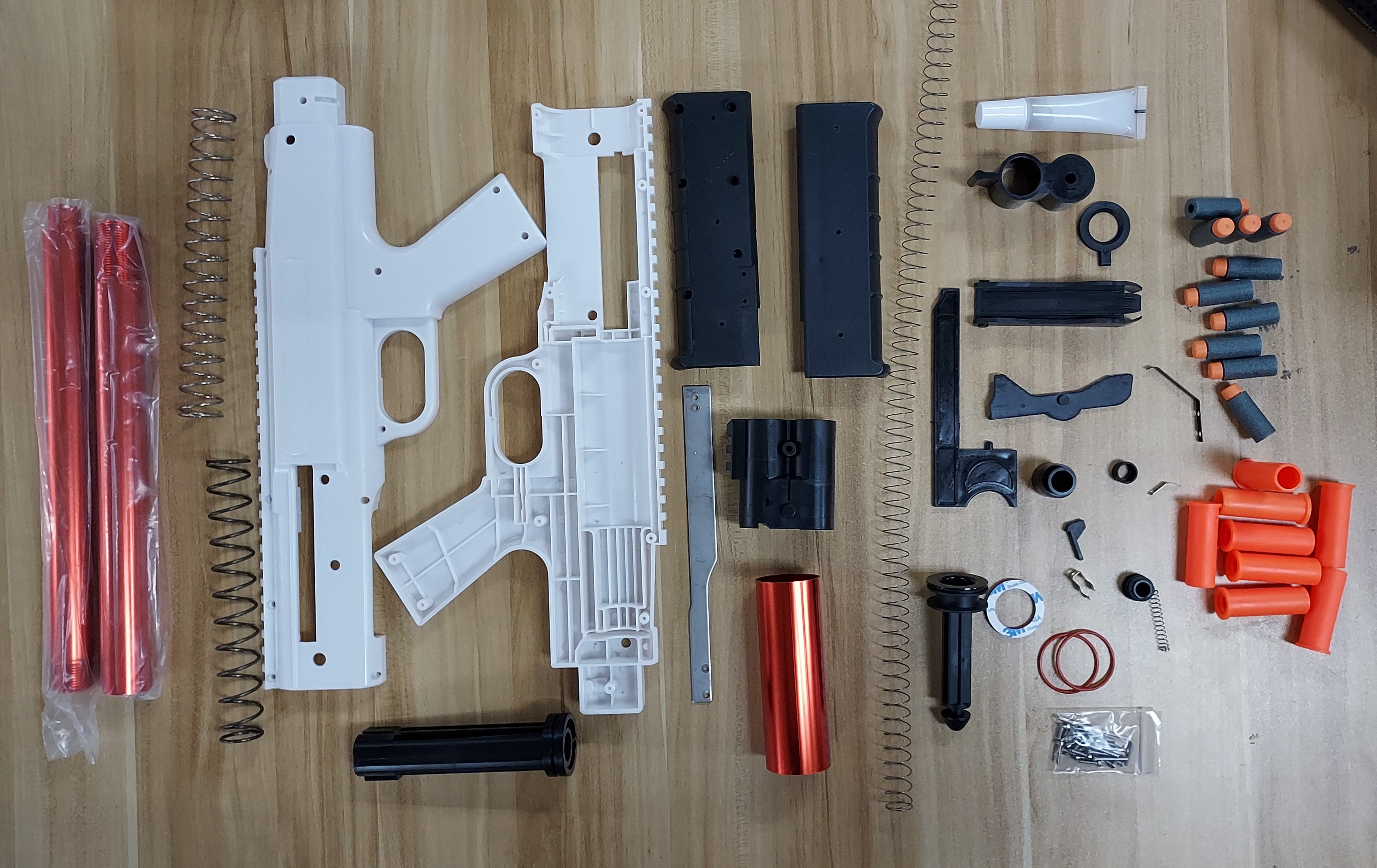
Before we begin with step 1, do check that all of the parts are inside the box and there are no missing pieces. The picture below shows all of the parts and items that are found inside your purchased Firefly box.
Step 1: Cleaning the excess burrs from parts
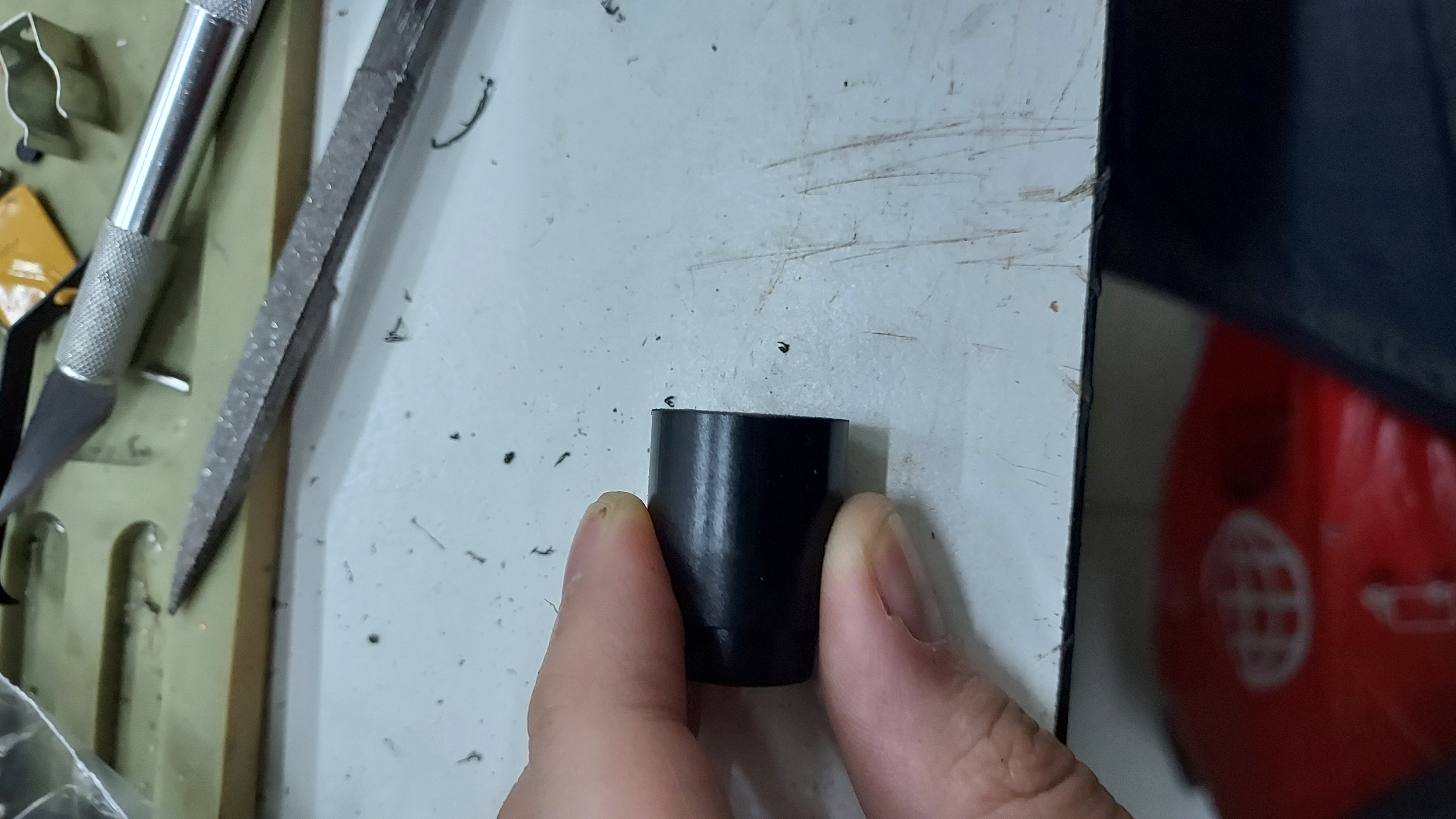
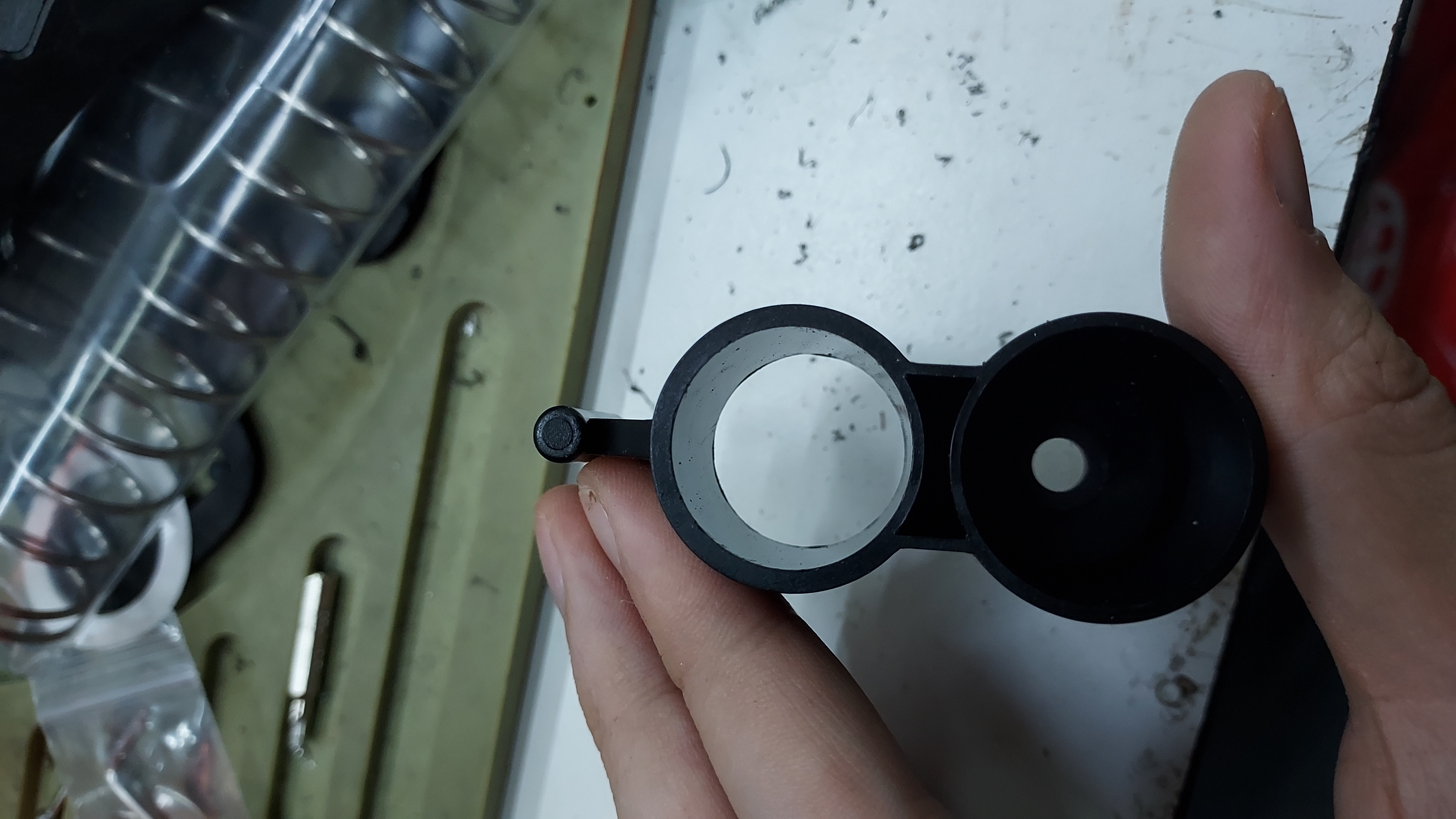
Some of the items of the Firefly unit may have excess burrs that may affect the performance of the blaster or prevent the proper blaster completion.
The few main pieces that affect the Firefly blaster V2.5 Assembly are the Plunger tube, Magazine tube Follower piece, Trigger piece, Magazine Cap and also the Shell Stopper.
Plunger Rod |
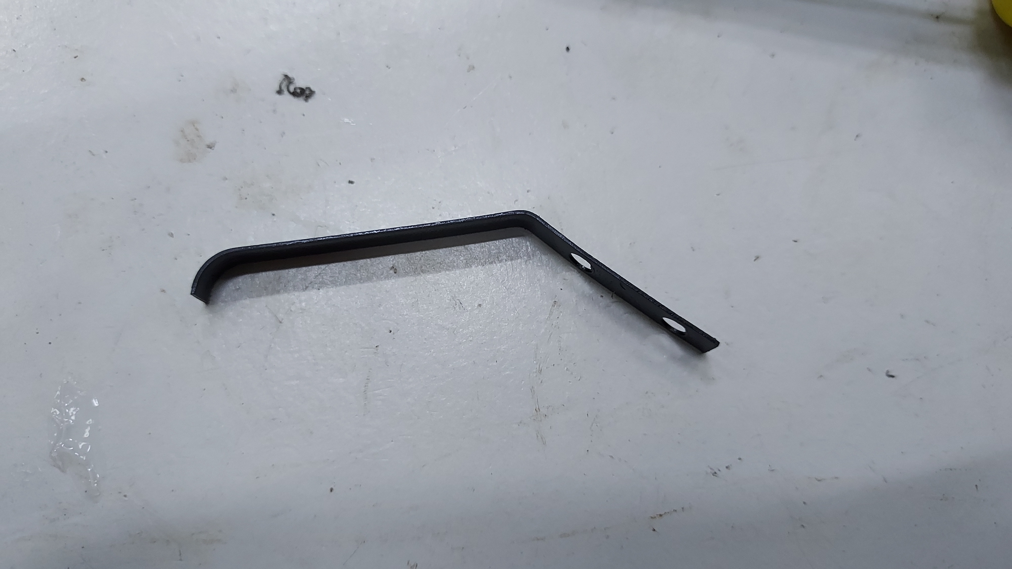
Shell Stopper |
Mag Tube Follower |
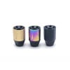
Magazine Cap |
Trigger |
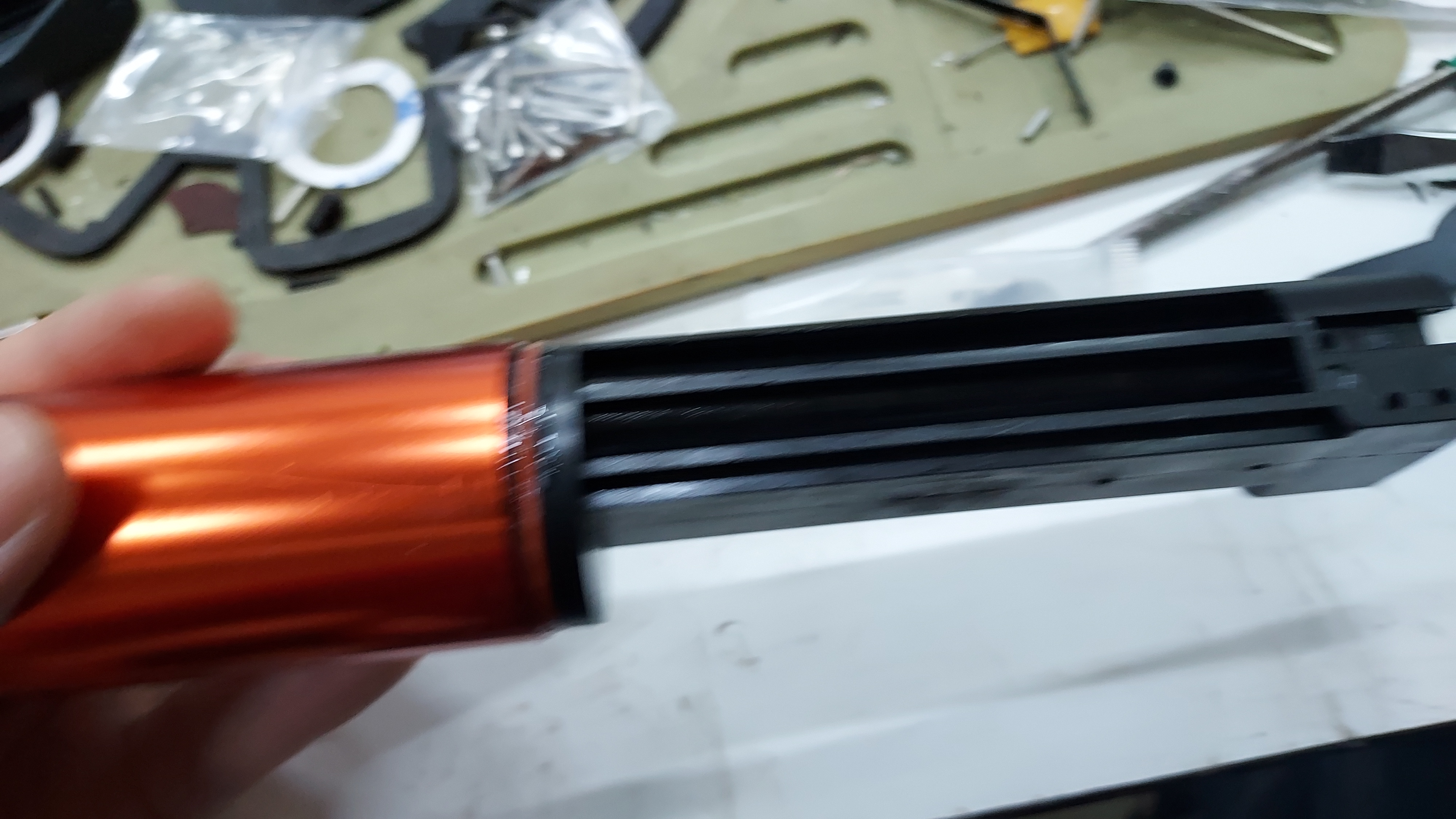
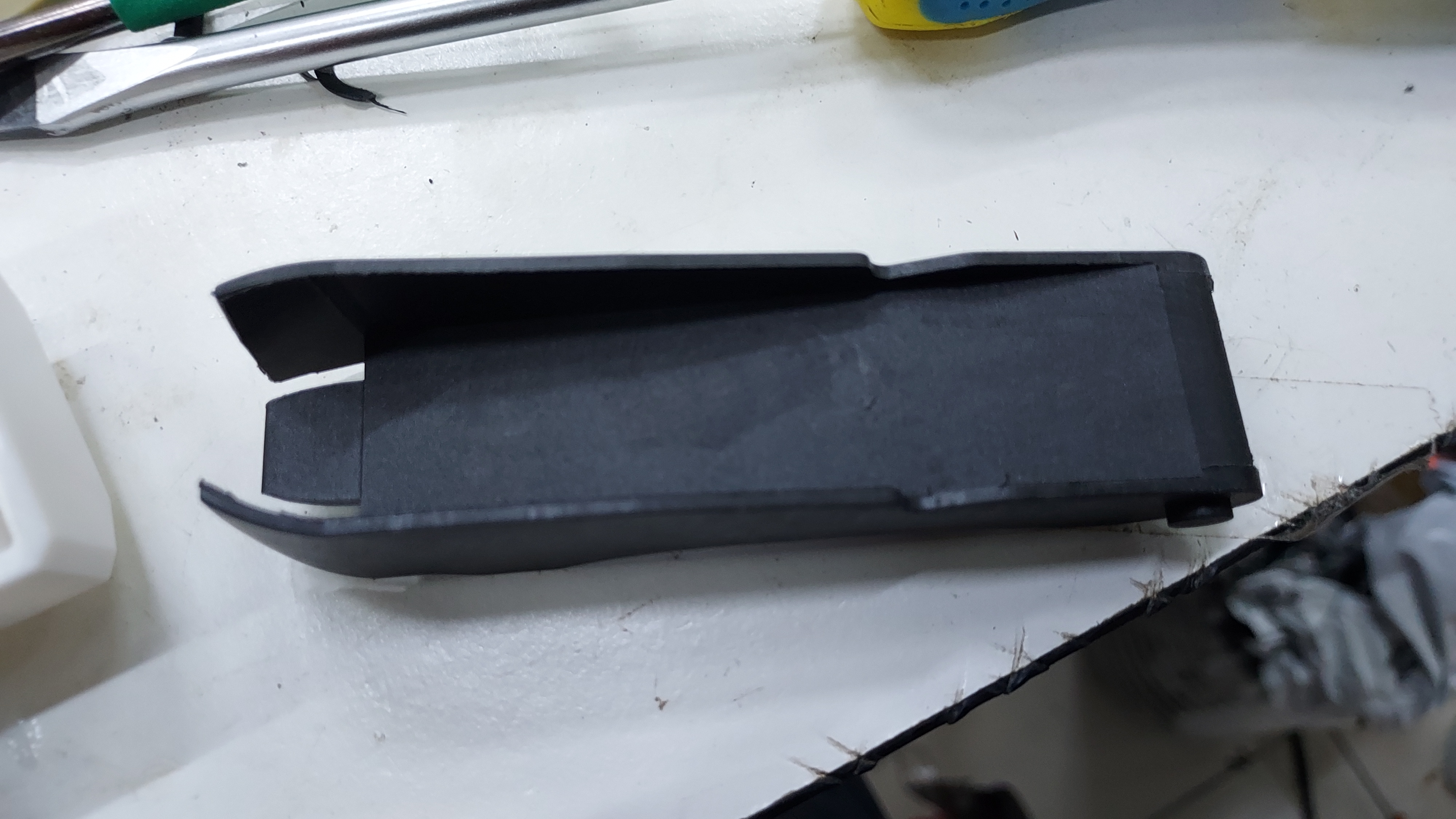
Plunger Tube |
.jpg)
.jpg)
.jpg)
.jpg)
.jpg)
.jpg)
.jpg)
Use a blade and sanding files to remove the excess burrs from the mentioned pieces and smoothen it for the proper movement of parts.
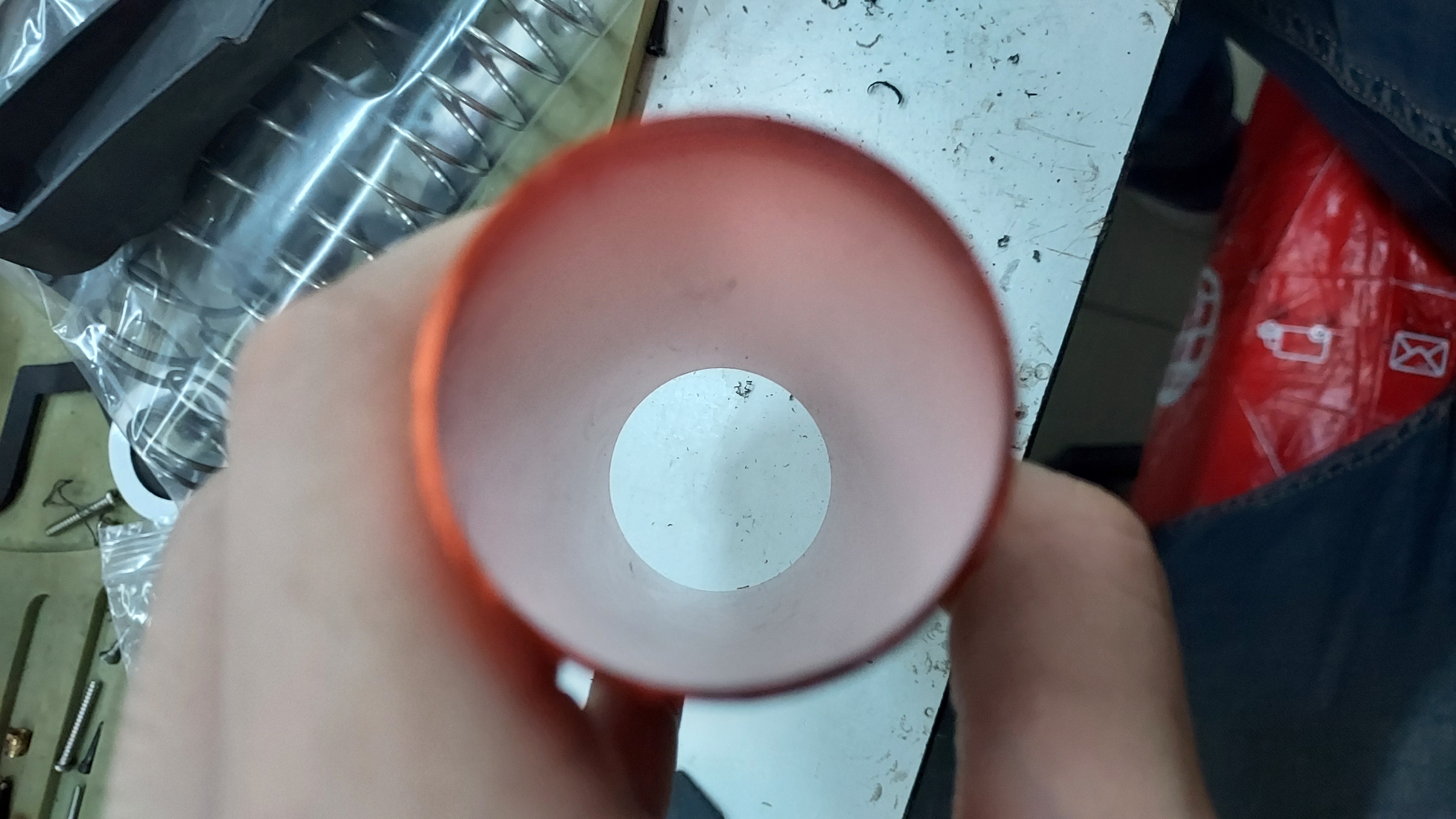
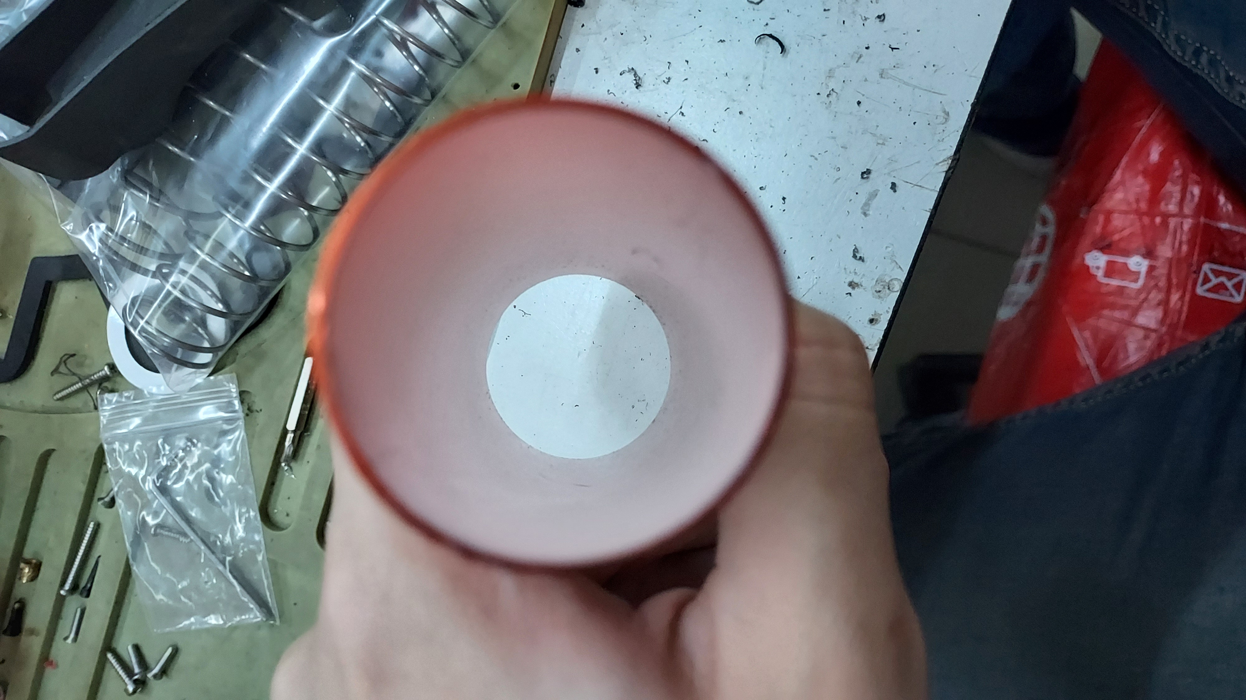
Examples of the cleaned items
Mag Follower |
Magazine Cap |
Plunger Tube |
Step 2: Preparing the Plunger assembly
Preparing the Firefly Assembly the most crucial piece to start with when building the firefly blasters.
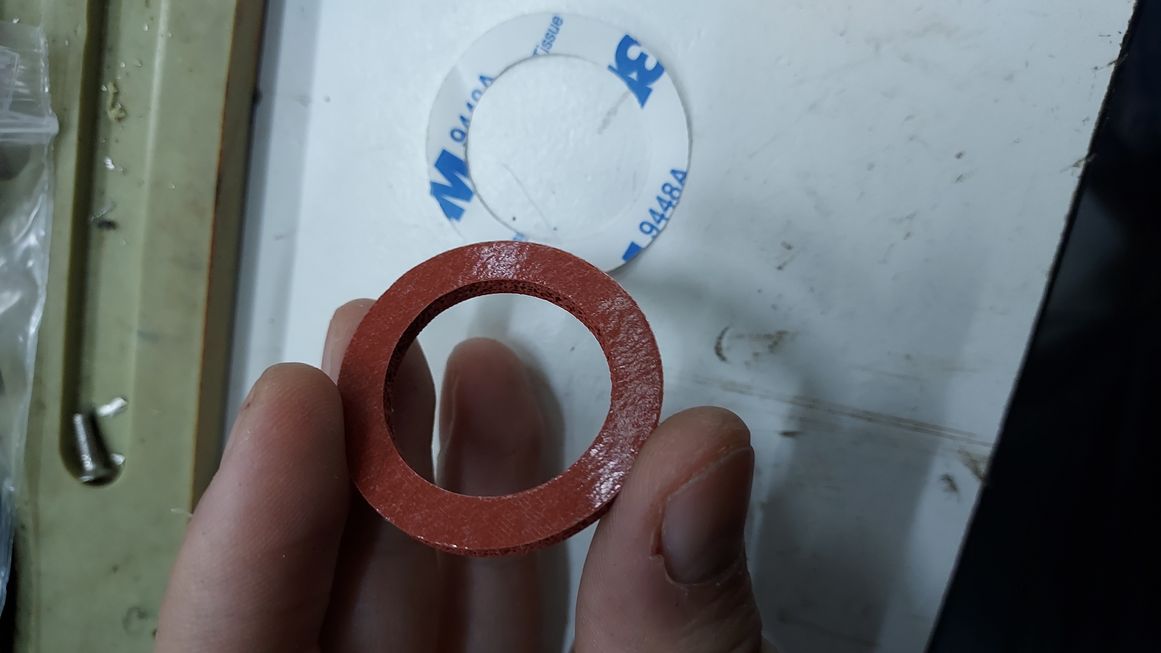
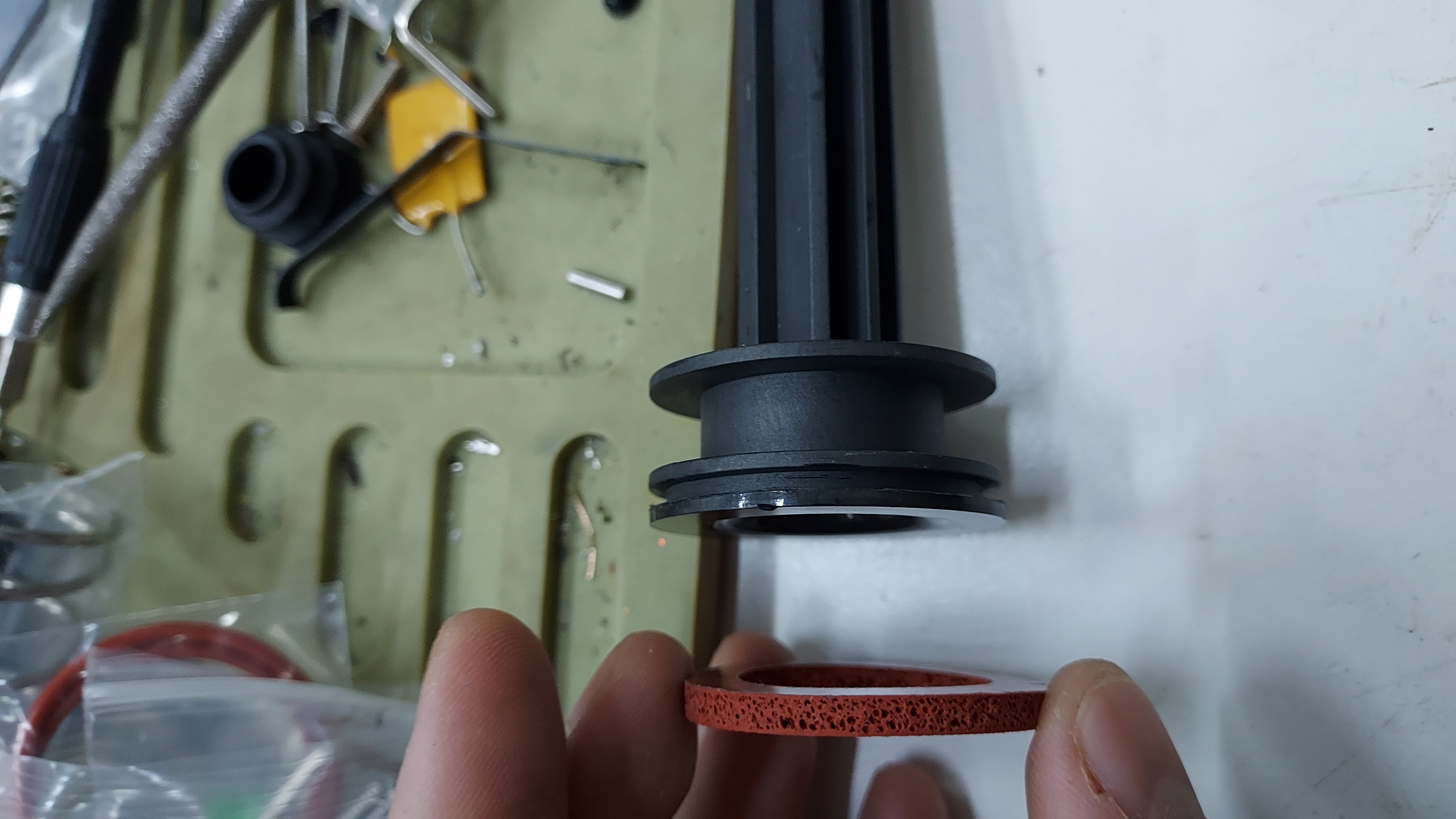
With the mentioned parts in the first step is now cleaned of burrs, we can start with the plunger rod. Firstly take the 3M shock padding that is provided to you in the small parts pack and place it into the plunger rod face.
To those who are reading this guide when you have purchased the first iteration of the Monkee Mods Firefly (Firefly V2.0), clean the grease from your plunger rod thoroughly and properly. Any left over grease on the plunger rod can completely negate the sticky part of the shock padding and making it just another rubber piece.
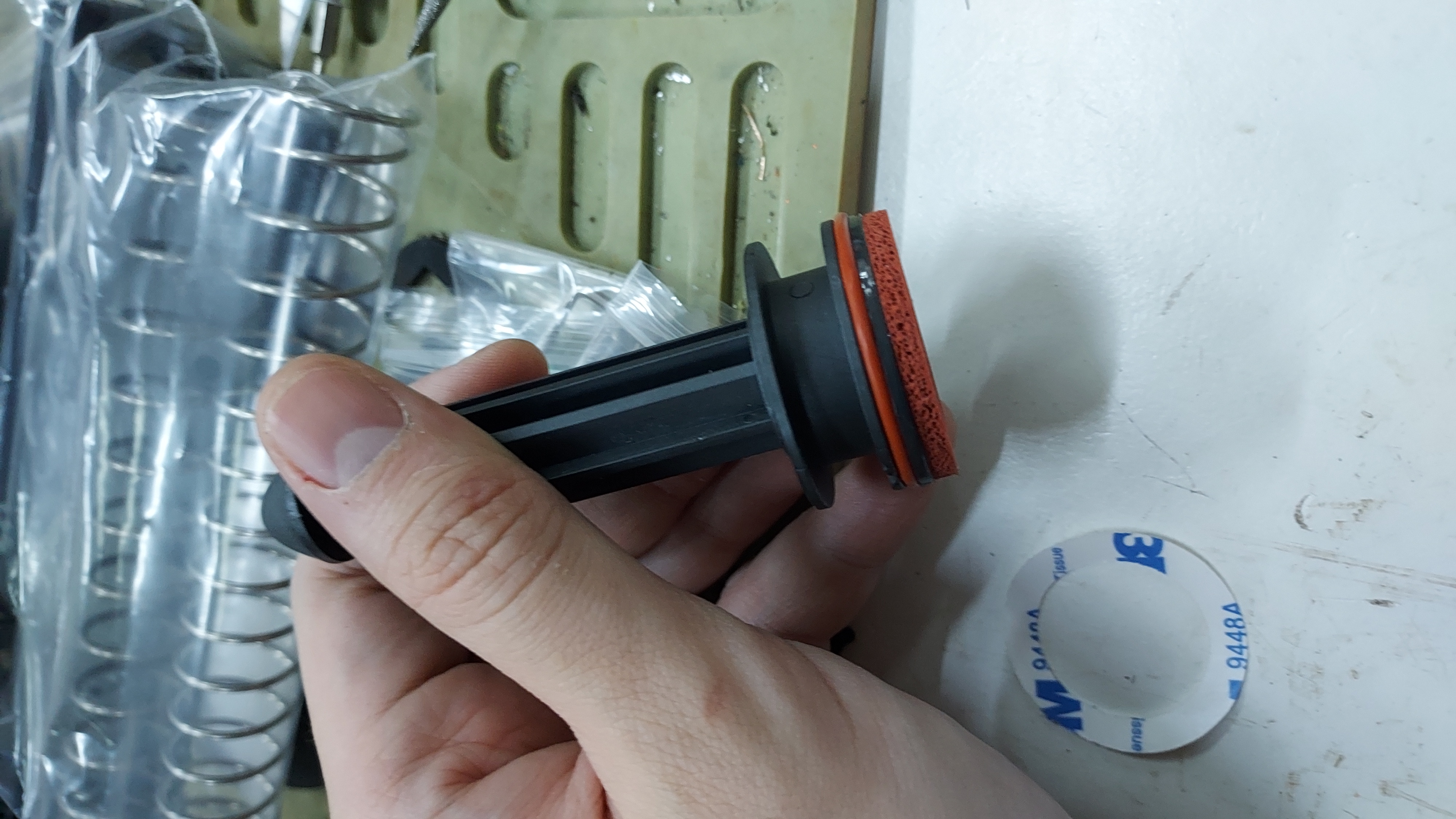
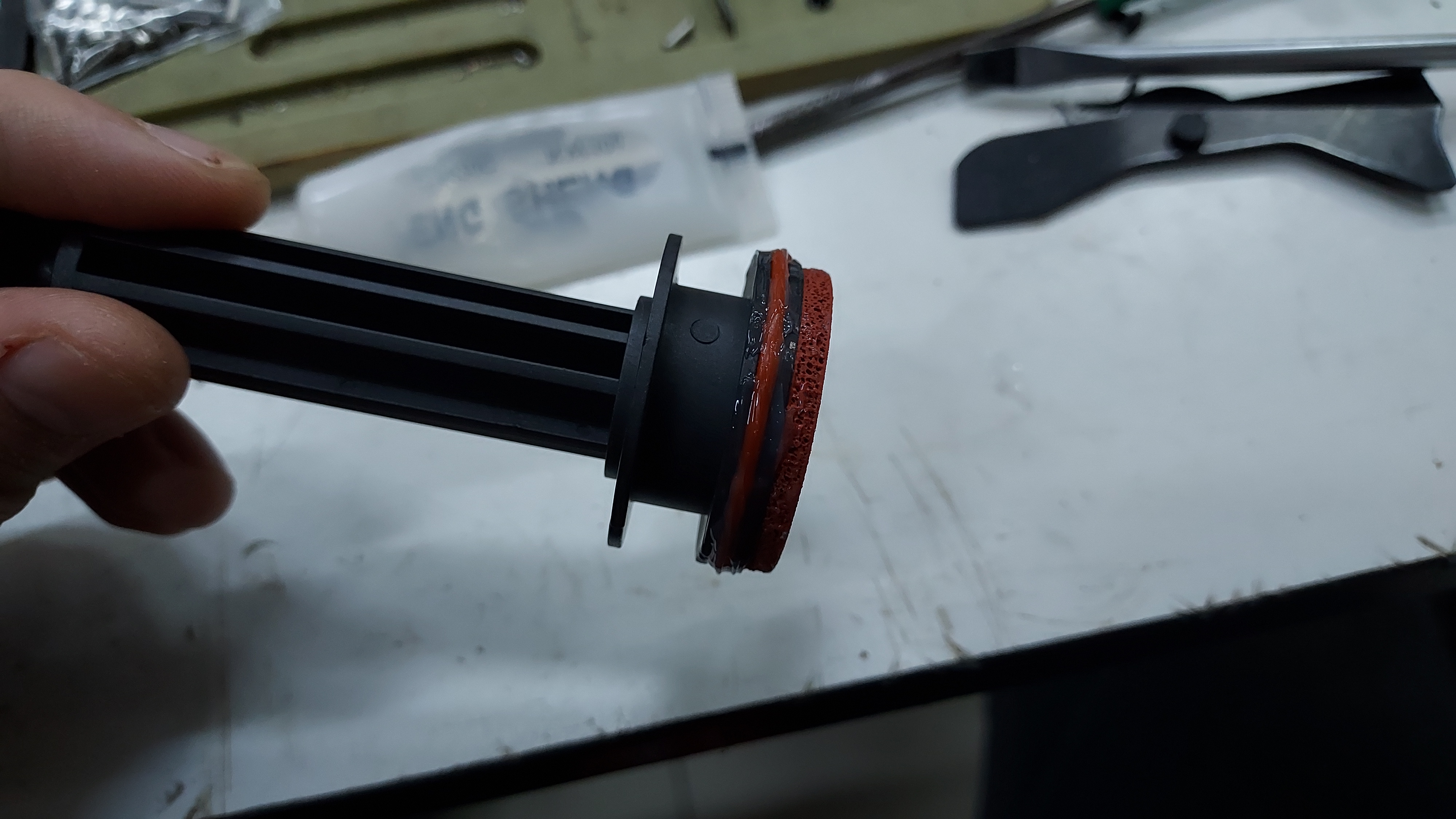
Once the shock padding is placed on the face of the plunger rod, place one of the o-ring pair on to the plunger rod groove. The end result of this plunger rod build will be as shown in the picture below.
After completing the plunger rod piece, place the last remaining o-ring piece to the breech unit.
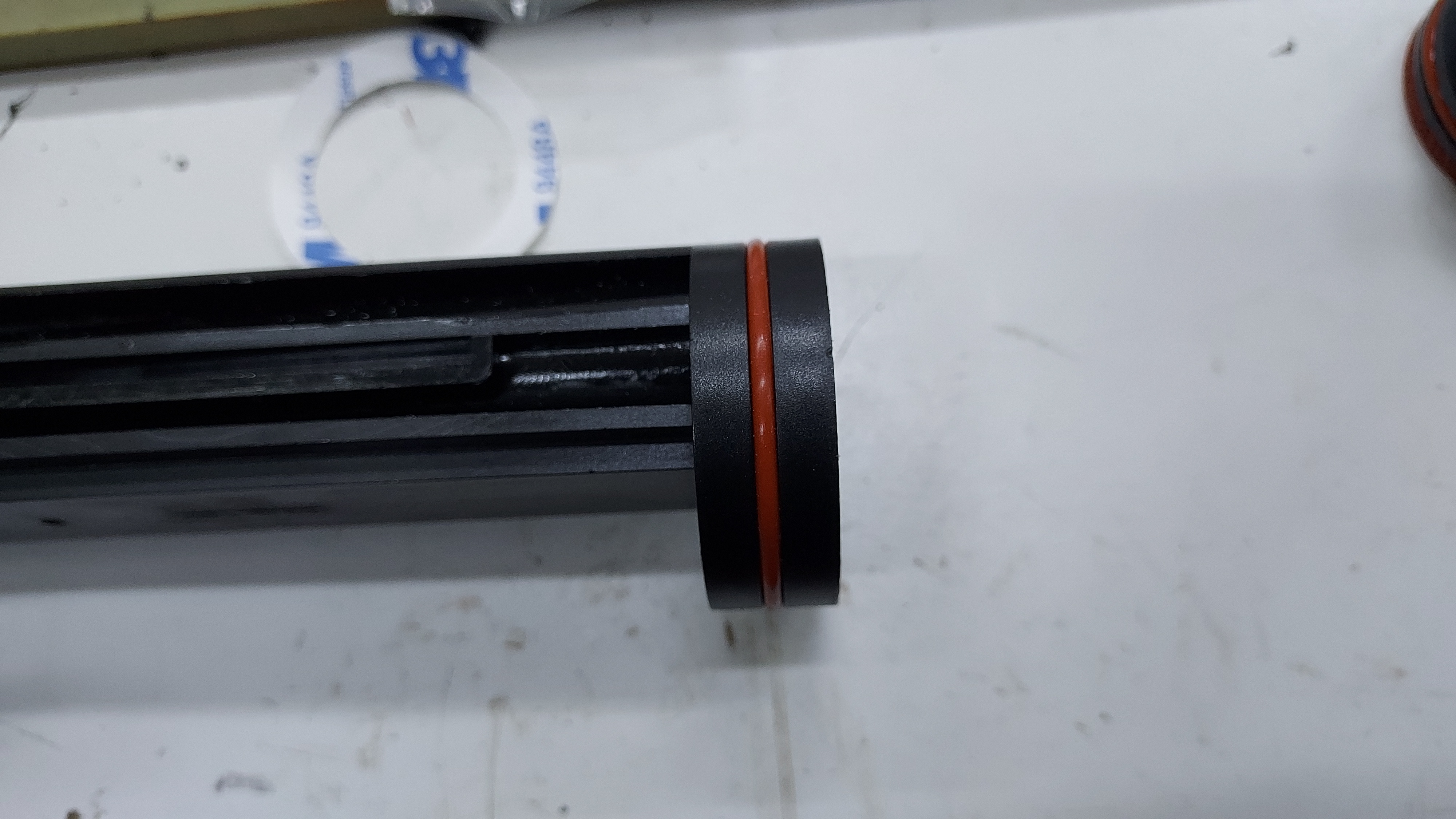
Try to place the o-rings into the grooves of the breech and plunger rod to the best possible position.
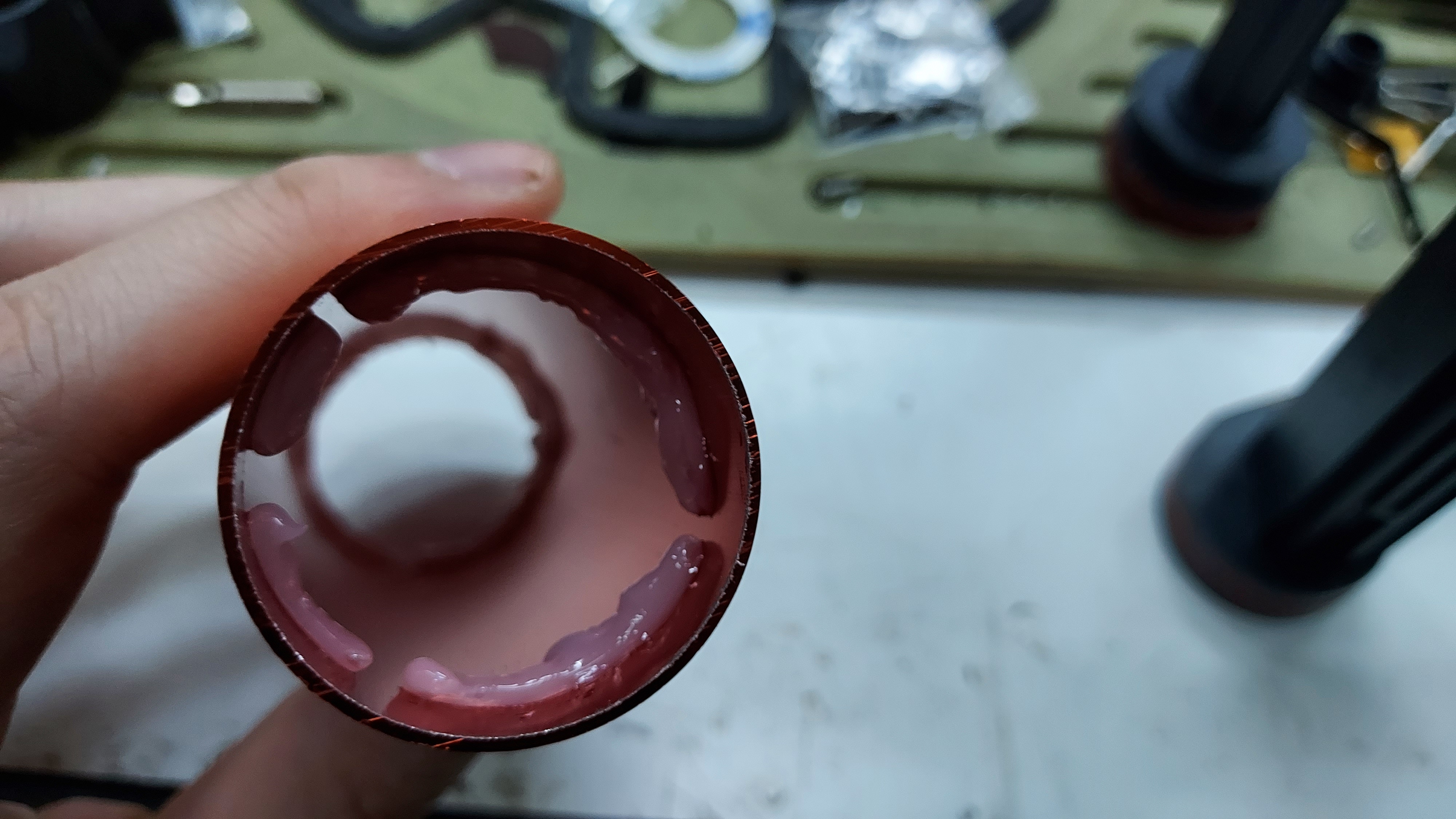
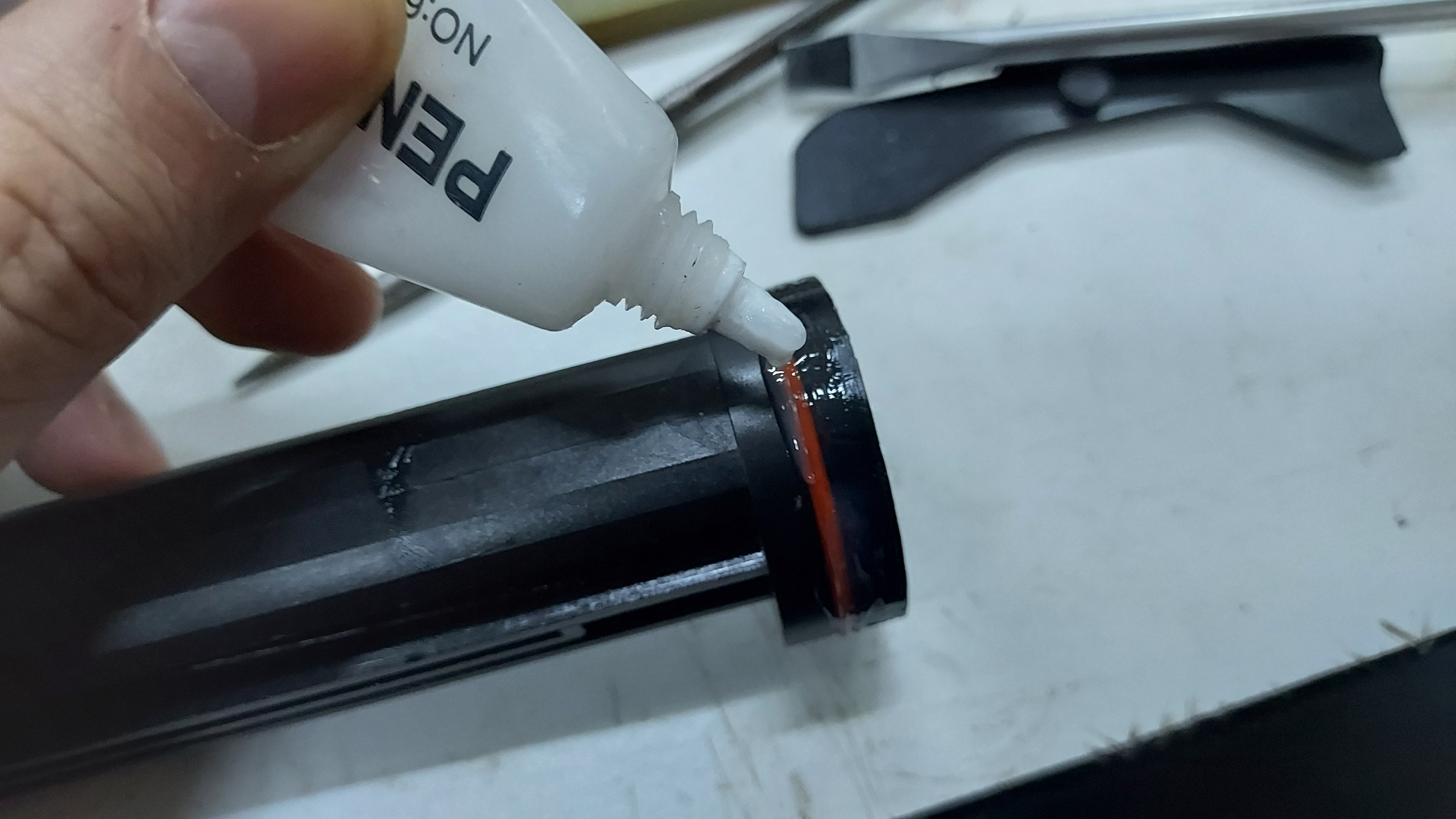
Once the O-rings are placed properly, it is time to place the breech gasket into the breech cut-out located at the front part of the breech.
The breech gasket can be secured better using either super glue or the UHU Multi-purpose glue. Do NOTE if you use UHU glue, give it 12 hours to a day for the glue to cure and harden.
.jpg)
In this guide we'll be using super glue to secure the breech gasket to the breech.
The next part in this step is building the Magazine tube follower.
These two pieces, the magazine tube follower and the cap are found inside the small parts package. Using the mallet, hammer the cap onto the magazine tube follower. There will be a bit of the fin piece coming out from the mag follower cap. Do not worry as it is standard when trying to fit the cap into the follower. By the end you should have a magazine follower that looks like the piece shown in the picture below.
Now with the parts completed, we can start putting them together.
Part 3: Assembling the plunger tube.
Firstly take your cleaned plunger tube and lubricate the inner parts with some grease. You can use the grease that is provided to you inside the box or you can use any silicone grease bought from hardware shops to lubricate the plunger tube
Provided Grease tube |
SuperLube Silicone grease (Can be purchased in your local hardware store) |
.jpg)
.jpg)
Do place a ring layer of grease on both sides of the plunger rod. You can also spread the grease around the inner wall of the plunger tube with the help of a brush.
Next, place some grease on the O-ring part of the Breech and plunger rod. The grease helps the breech and plunger rod to slide in the plunger tube properly and prevent the o-ring from being eaten and cut by the plunger tube.
Lubricate oring and breech |
Lubricated breech and o-ring |
Lubricated oring and Plunger rod |

Once the breech and plunger rod are lubricated, place them together inside the plunger rod.
|
|
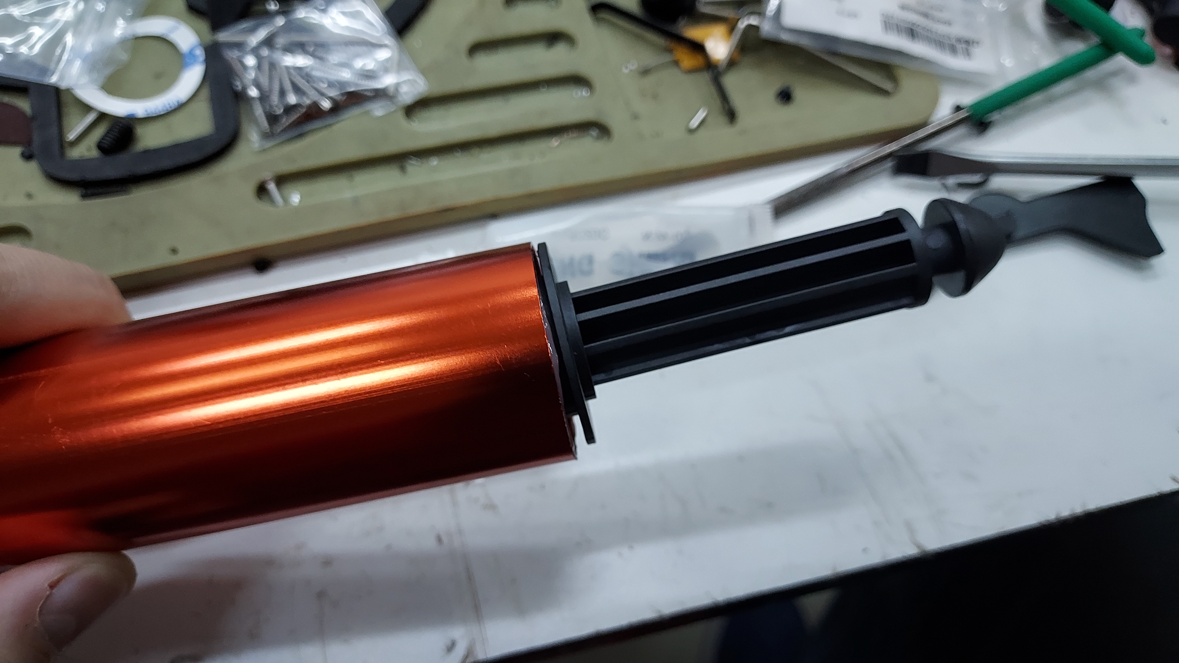
Once both breech and plunger rod are in the plunger tube, move the plunger tube piece with the breech and plunger rod placed together. This is to ensure that the grease/lubrication used is working and the pieces are moving throughout the plunger tube smoothly.
Now we can start with the Firefly main body,
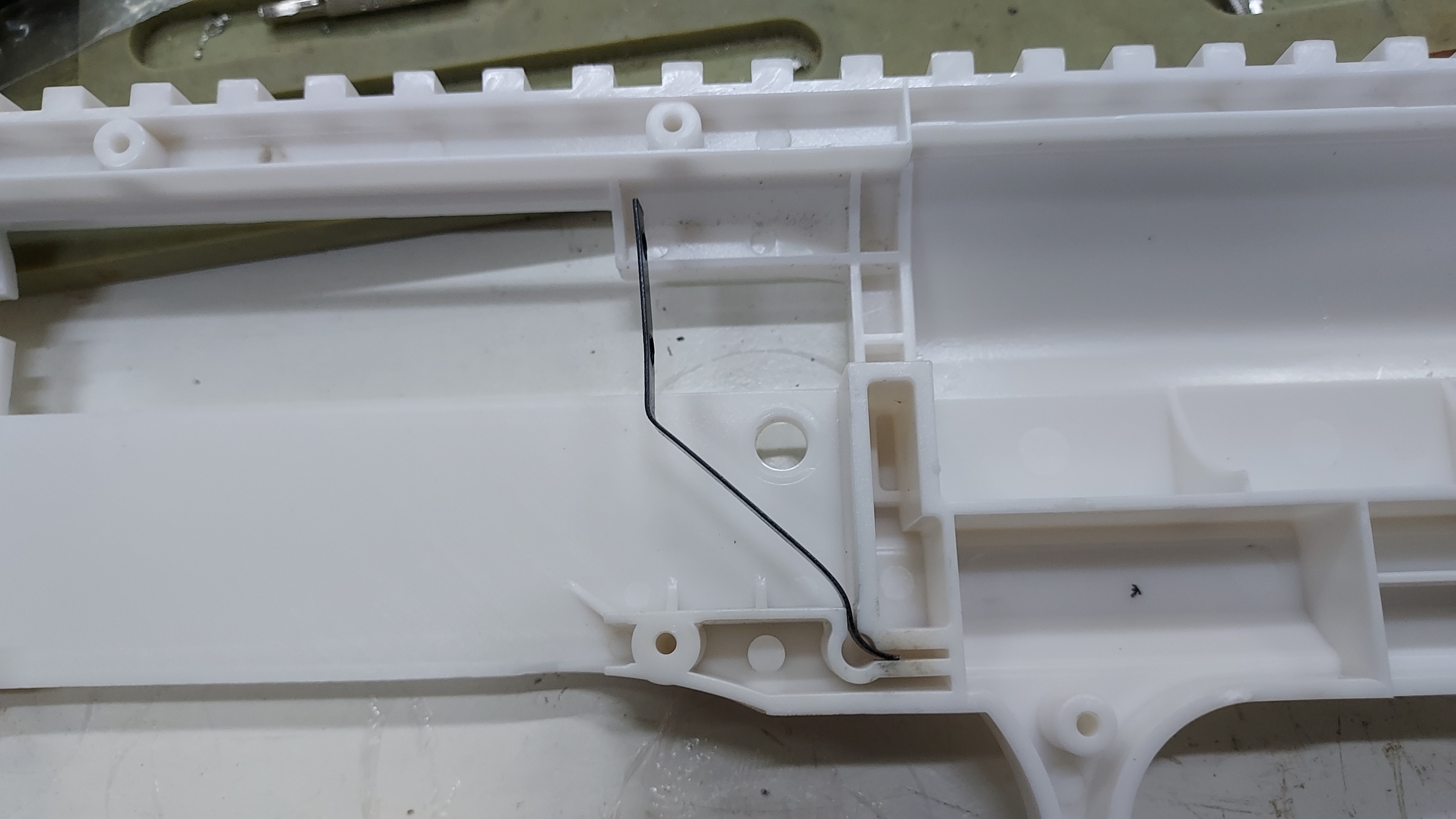
Take the right side of the receiver shell and place the shell lifter spring into the hole cutout. Bend the shell lifter spring to this position in preparation to place the shell lifter with the plunger tube assembly of the firefly.
Shell lifter spring |
Prepared shell lifter spring in right side of receiver shell. |
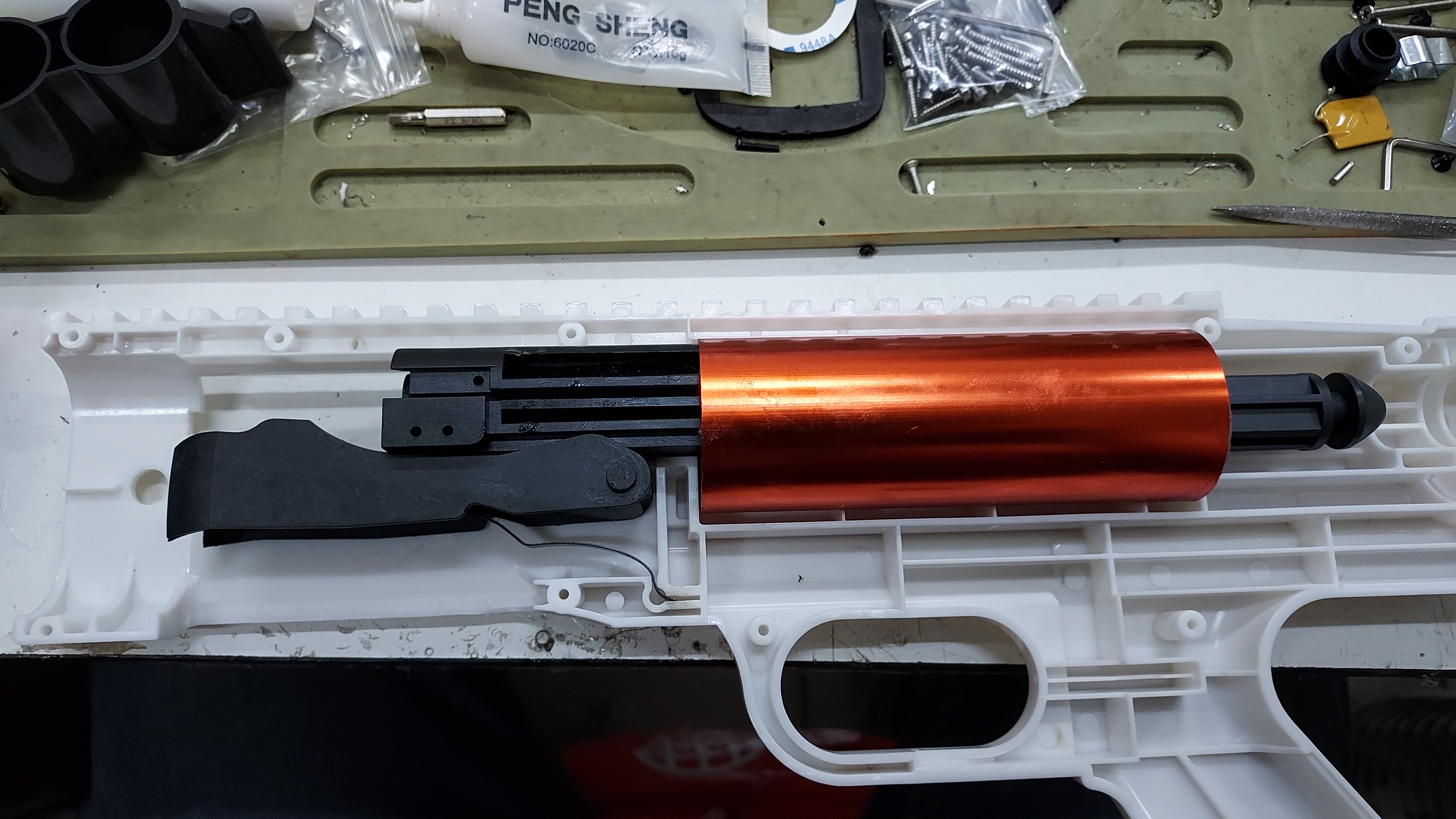
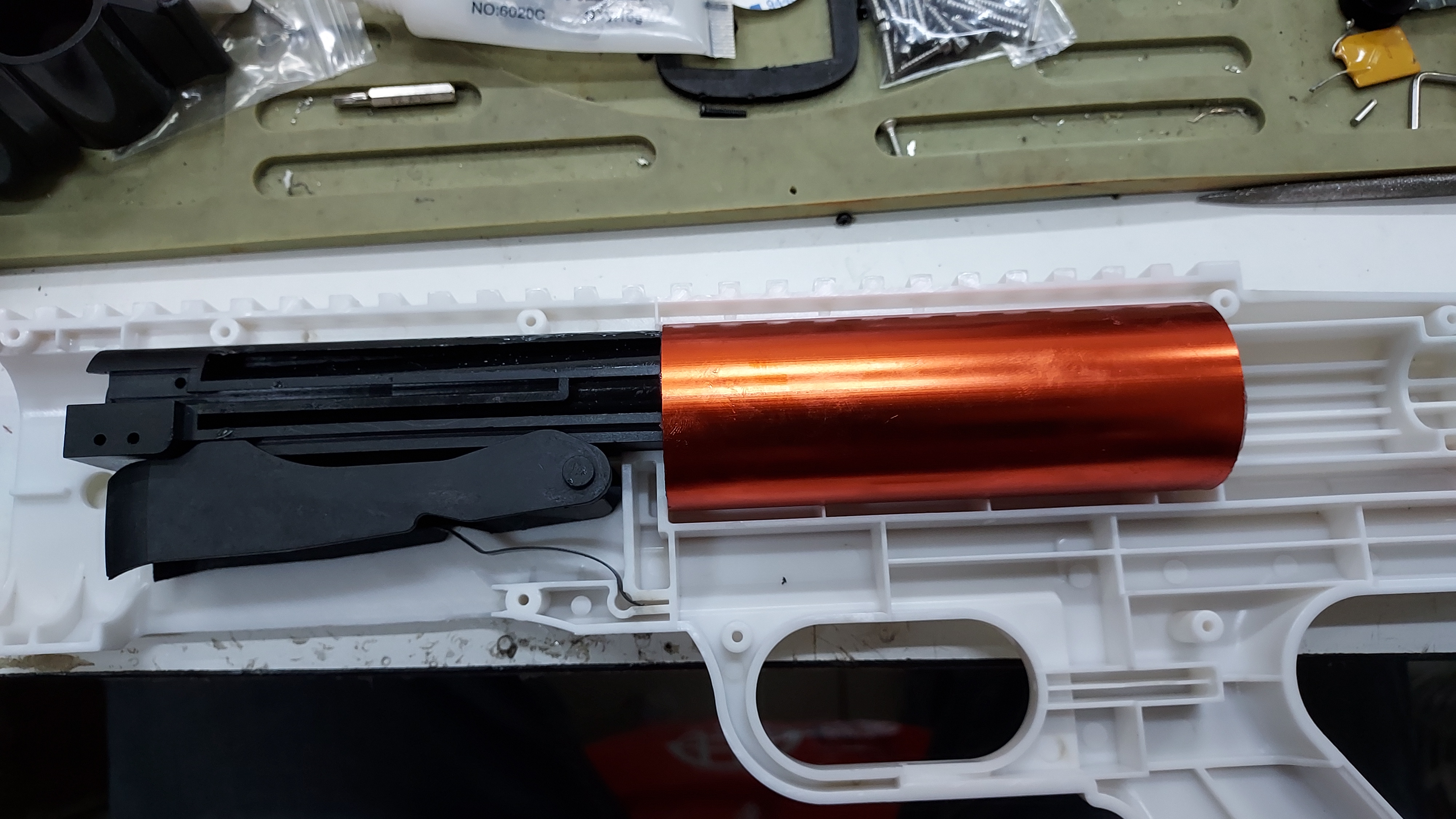
Now bend the shell lifter spring a bit more to fit in the shell lifter piece. Once the shell lifter is in place, place the plunger tube assembly in the plunger tube cut-out area of the receiver shell. You can push the plunger rod further in to ensure the shell lifter sits properly on the breech unit.
Shell lifter piece |
The placement of the plunger assembly into the right side of the receiver shell. |
Ensuring the shell lifter sits on the breech properly |
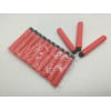
Now we shall install the main spring of the Firefly. You are given 2 choices of spring inside your Firefly box, the 5 kg spring and 12 kg Spring. In this guide, we will be using the 5kg spring to build up the Firefly. For those that wish to use the 12kg Spring we will give 'NOTE' pointers on what is required compared to the 5kg main spring.
.jpg)
(5KG Spring: Thinner silver main spring with more coils, 12KG Spring: Thicker wire diameter with less coil and shorter)
Place the 5 kg spring all the way inside the plunger tube assembly. Compress the main spring to fit into the receiver shell. Hold down the main spring and plunger tube to prevent the tube and shell lifter from flying out of their positions. (NOTE!!: This is especially crucial when placing the 12KG main Spring. If you cannot hold it down with 1 hand like you see in the picture below, please ask for aid to complete the blaster with another person and use 2 hands to do so). Once the main spring is held down properly, place the catch plate and catch plate spring at the cut-out points near the butt end of the receiver shell. (NOTE!!: If you're installing the 12 kg main spring inside your Firefly blaster, please do them inside a box. This is to prevent the small spring and parts flying out of the hold and also prevent it from being lost. this can also be done using 5kg, 7kg, and 10kg main springs)
 1.jpg)
(5kg main spring now held down as the catch plate, catch plate spring and trigger spring is placed)
As shown in the picture above, do place the trigger spring at the square spring placement for the trigger. This new trigger spring is much longer compared to our old trigger spring. This is done to ensure that the trigger will no longer 'sticky' inside the built receiver shell. Then place the trimmed trigger with the spring guide piece of the trigger placed in together with the spring. There's no need to compress the trigger spring to make it fit inside the trigger cut-out area of the receiver shell.
(DISCLAIMER!!: If you have the shorter trigger spring, there is no need to do the extra steps mentioned above. You can place the trimmed trigger with the short trigger spring onto the trigger and spring cut-out of the receiver shell.)
 3.jpg)
(The trimmed trigger now placed in position.)
Now using the left side of the receiver shell, close the receiver shell piece by closing it at the main spring area first. By doing this, you can prevent the main spring from flying out of position when releasing your hold on the main spring. Once the receiver shell is closed properly hold onto the grip area to prevent the shell from opening and flinging all the small parts about (NOTE!!: This is very IMPORTANT for those who want to place the 12KG Main spring)
Left side Receiver shell |
Receiver shell closed completely. |
 2.jpg)
 4.jpg)
If the Main spring is ajar from position when the receiver shell is placed, use a thin screw driver or a thin metal piece to ensure the spring is place properly. Do the main spring adjustment while holding the grip end of the receiver. (NOTE!!: For the 12 KG Spring, please use a slightly thicker screwdriver to help adjust the spring into place). With the left receiver piece in place and slowly squeeze the trigger down to complete the plunger assembly build of the firefly.
 5.jpg)
(DISCLAIMER!!: There is no need to do this if you have the shorter trigger spring.)
Do ensure that the receiver shell is closed properly by looking at 3 key areas of the receiver piece
Trigger point |
other holder point of the Shell Lifter (If it is ajar, use a flat head screw driver to push the shell lifter piece to make it sit inside the hole) |
Top rail area. |
 6.jpg)
 7.jpg)
 8.jpg)
 9.jpg)
(Hex head Tapered screws)
Use 7 out of the 13 screws provided to secure the grip piece.
 10.jpg)
Try not to over-tighten the screws, as this can make the trigger activation to be harder. With the grip end of the Firefly receiver shell secured, we can now continue on with the rest of the Firefly with relative ease.
Part 4: Completing the Firefly Receiver
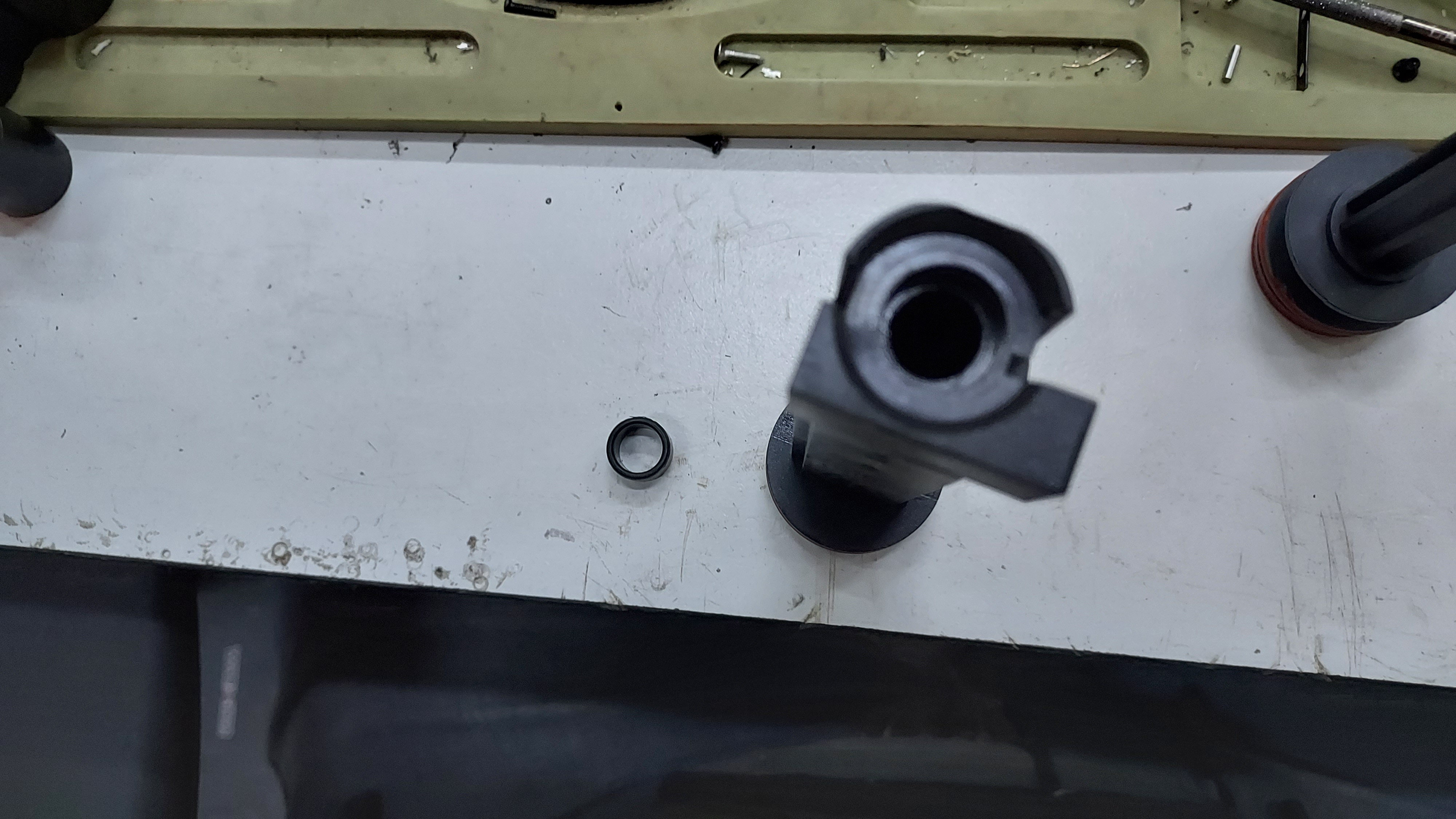
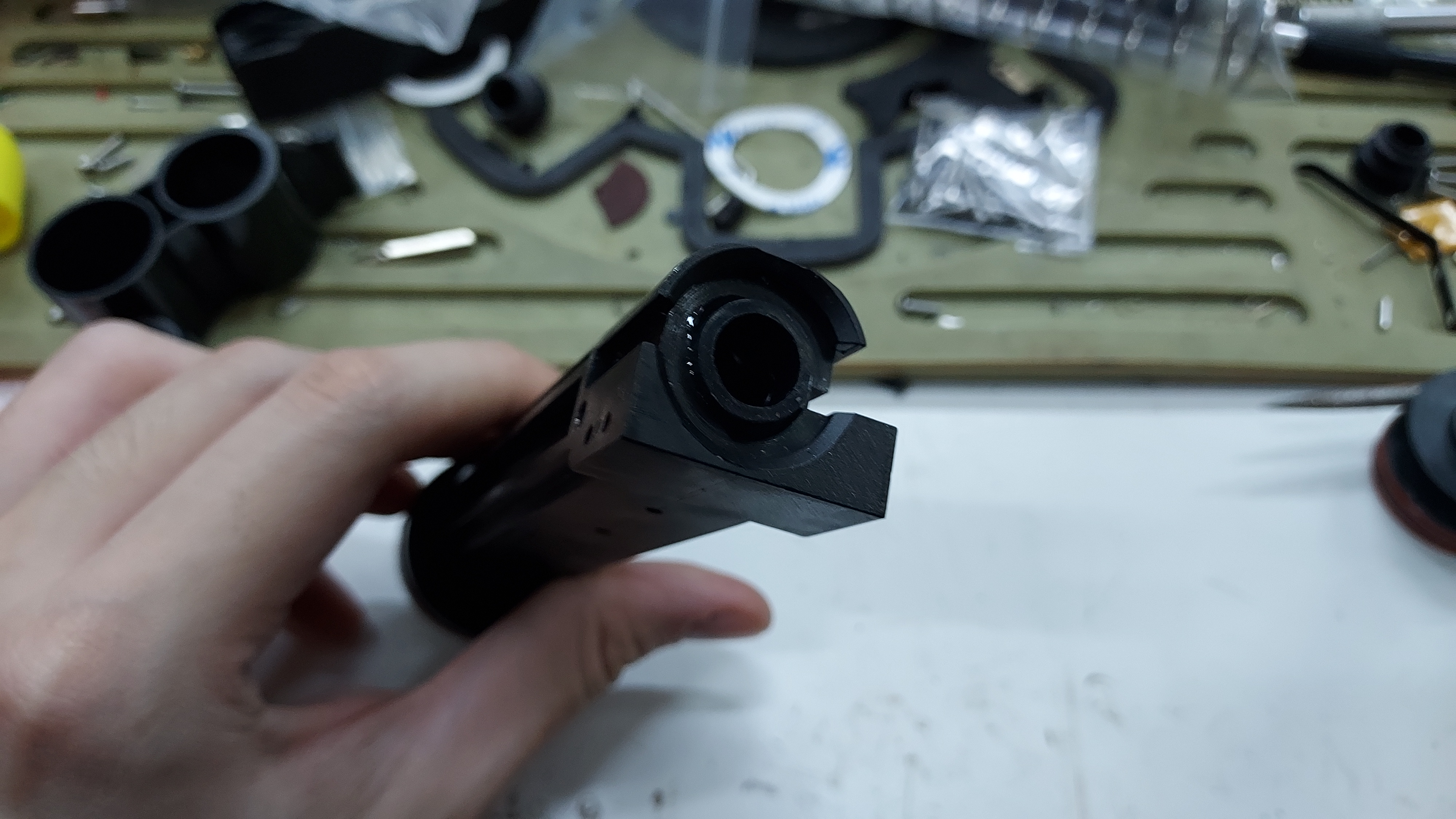
Now that the Plunger tube assembly is built in the receiver shell, we shall now complete the rest of the receiver shell with the remaining pieces of the shell stopper, breech adapter and the extractor piece.
We shall start with the breech adaptor. The breech adaptor can be installed by lightly prying the receiver shell open and placing the breech adaptor into the holes at the front end of the receiver shell.
(Breech adaptor piece before installation)
The shell stopper is next and it is one of the thinnest part of the firefly blaster. It can be inserted on the left side holder point of the receiver shell, even when the receiver shell is built. Insert it through the gap made between the shell lifter and receiver shell piece itself. This can also be done when the breech adaptor is installed. the end result should be shown in the picture below
(Breech adaptor and shell stopper placed inside the receiver.)
With those pieces placed securely in their respective positions, complete the receiver shell by screwing in the last few screw points with the remainder of the receiver shell screws.
The extractor will be placed in the part with the breech on the right side of the receiver blaster. do place the extractor spring on top of the extractor piece and screw it down with the extractor screw. The extractor piece is one of the most versatile piece in the Firefly blaster. You can build it in together with the breech before making the plunger assembly, during the plunger assembly, after completing the receiver assembly or even after completing the entire blaster.
Extractor piece and extractor spring placed in the breech area. |
Extractor screw |
With all those parts placed and installed, the receiver piece is now complete.
Part 5: Completion
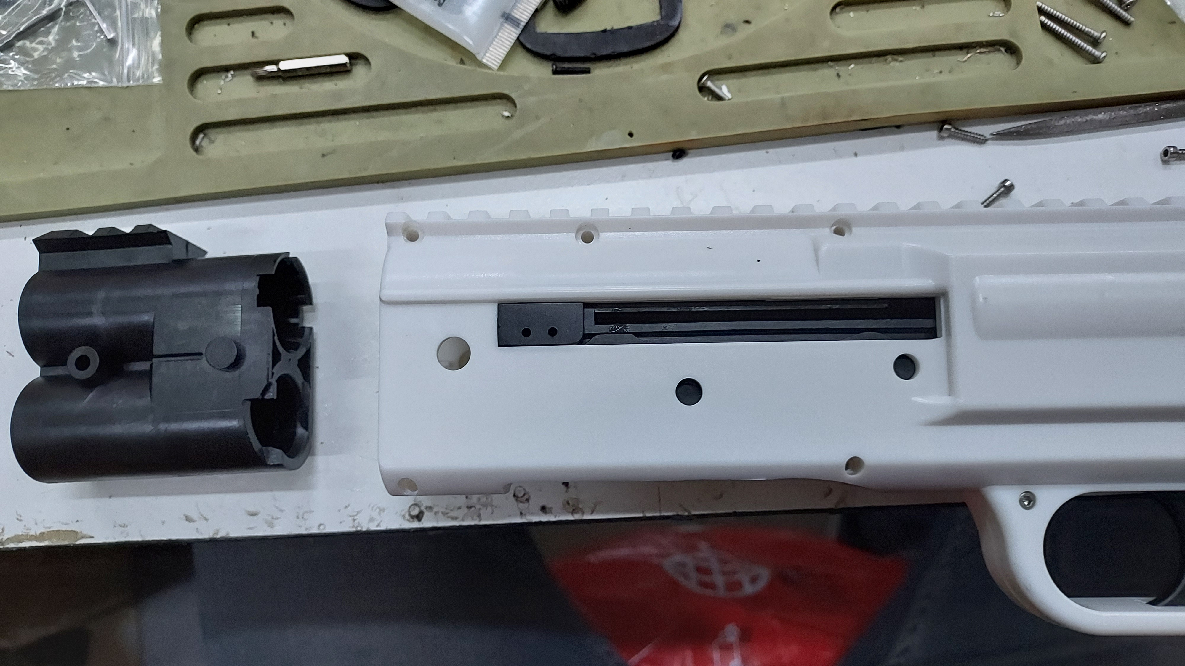
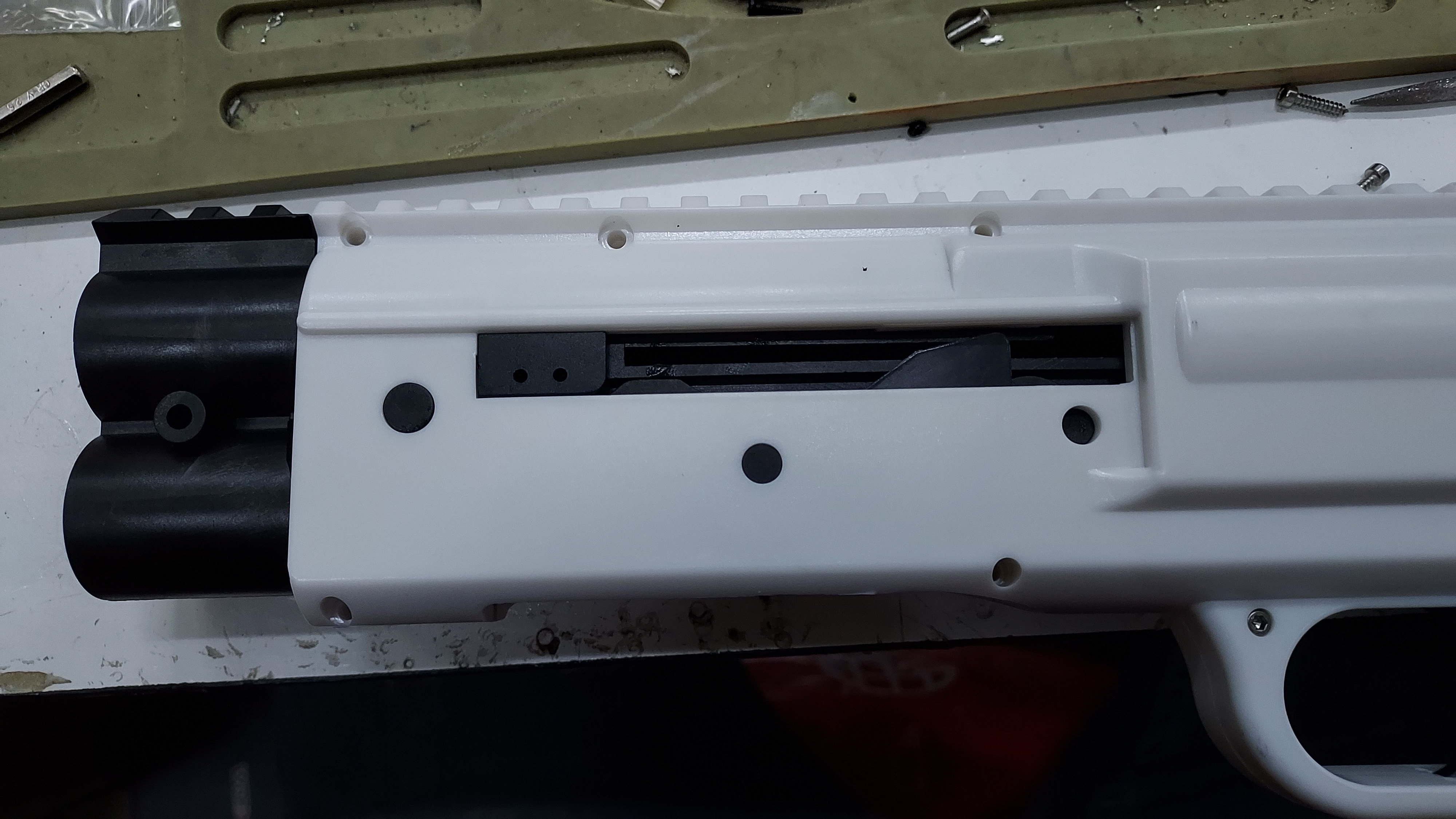
To complete the Firefly blaster build, the barrels and pump grip must be installed.
Firstly, place the magazine tube into the threaded barrel first. This is to ensure that the pump grip will be properly built on the mag tube.
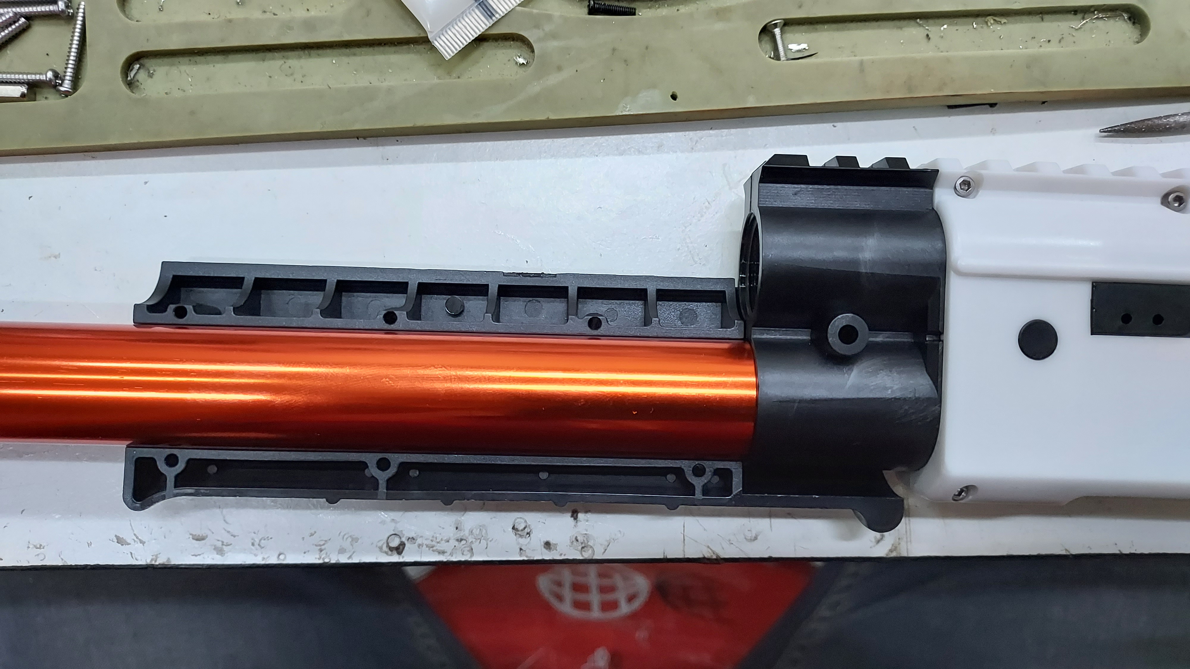
With the mag tube in place, you can now place the pump grip on the unit.
(Pump grip and screw pieces.)
Place the right side of the pump grip onto the magazine tube and then place the left side of the pump grip on top.
Right side of the pump grip placed |
Left side of the pump grip placed on the right side and screws placed on the ends of the pump grip. |
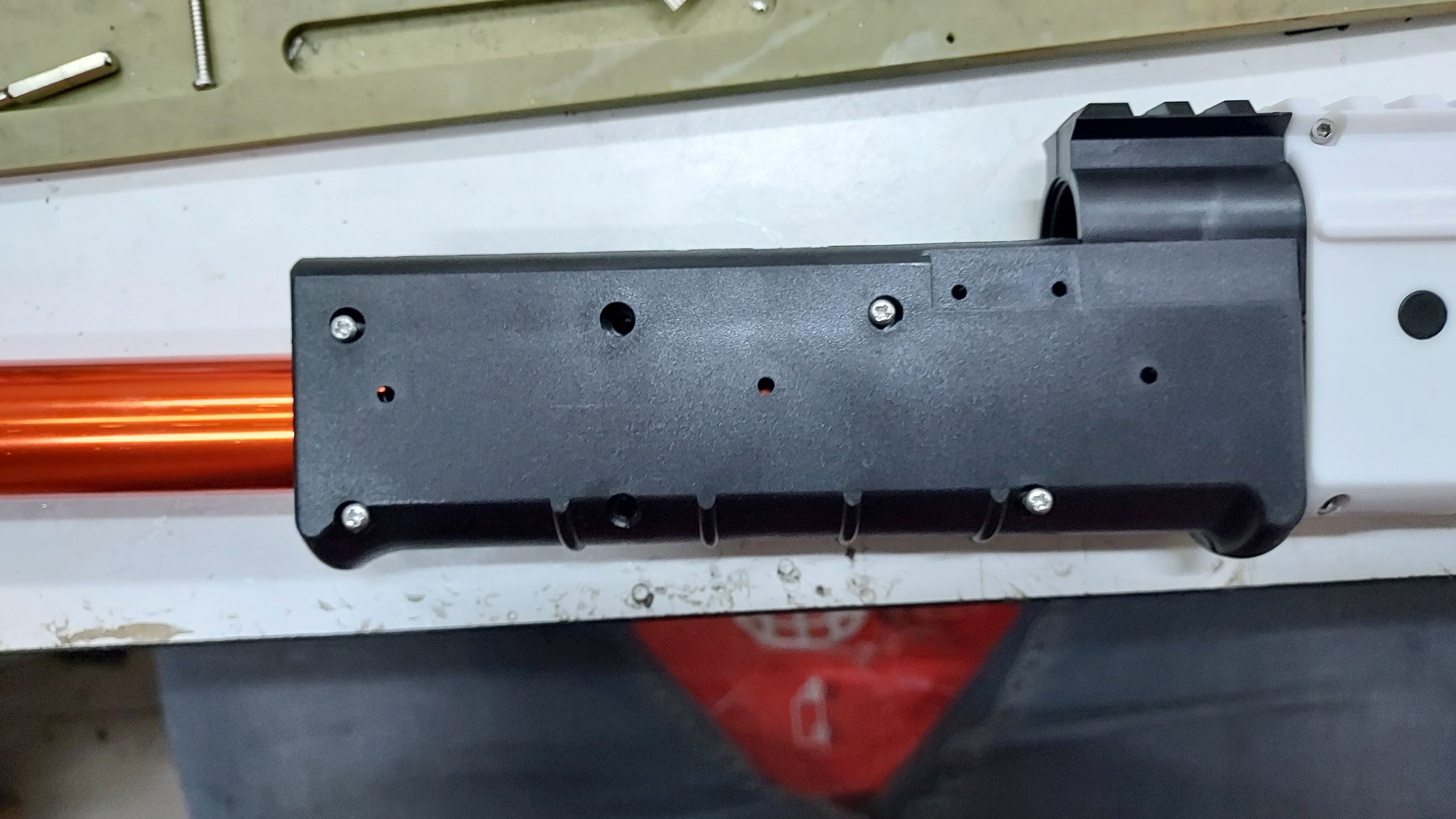
Place the screws at the ends of the pump grip to properly secure them, then screw in the central piece of the pump grip.
You can use either a cordless screw driver or the manual screwdriver to thread in the screws into the pump grip.
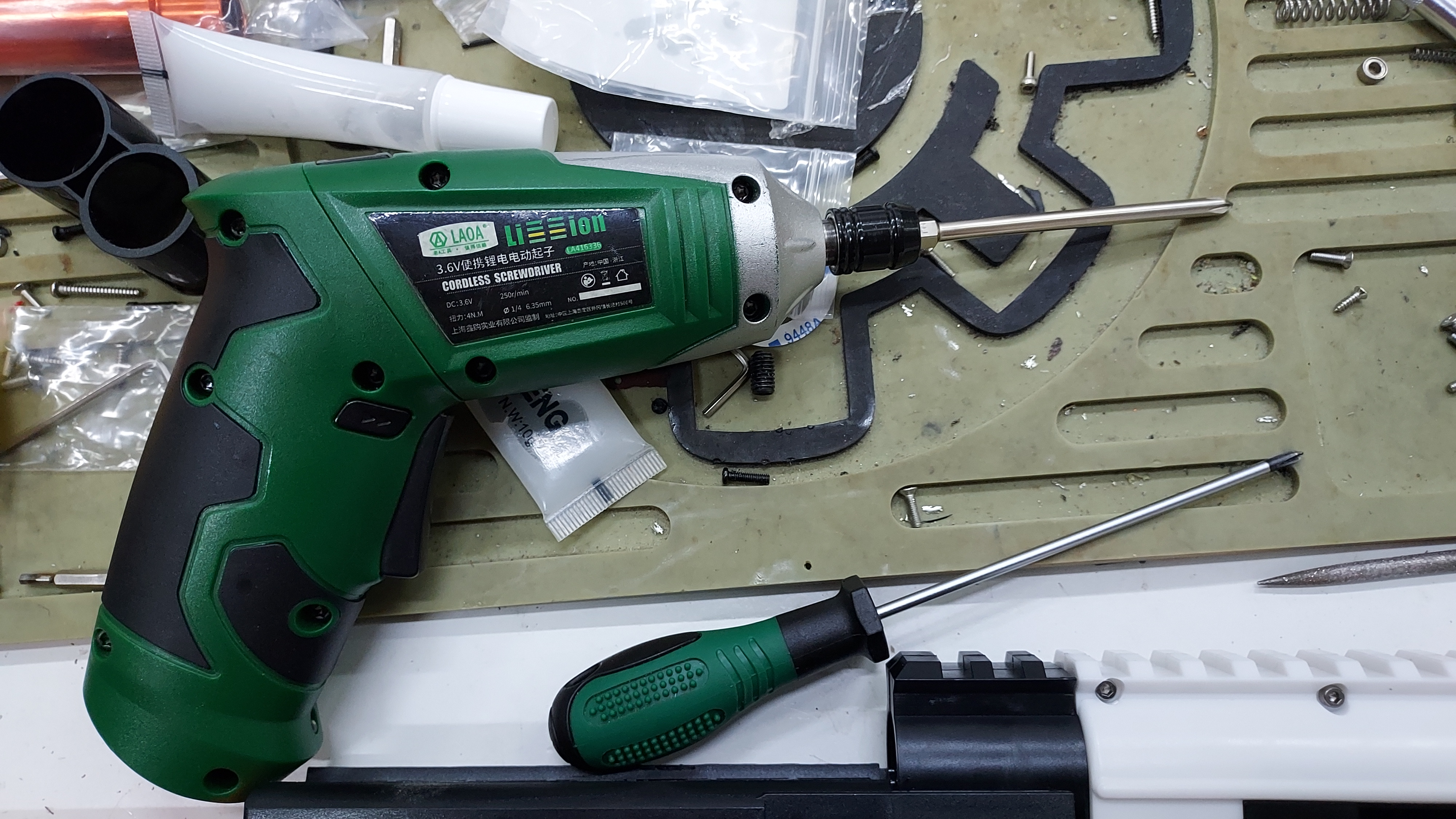
(Cordless screw driver with Phillips head and manual Phillips head screwdriver)
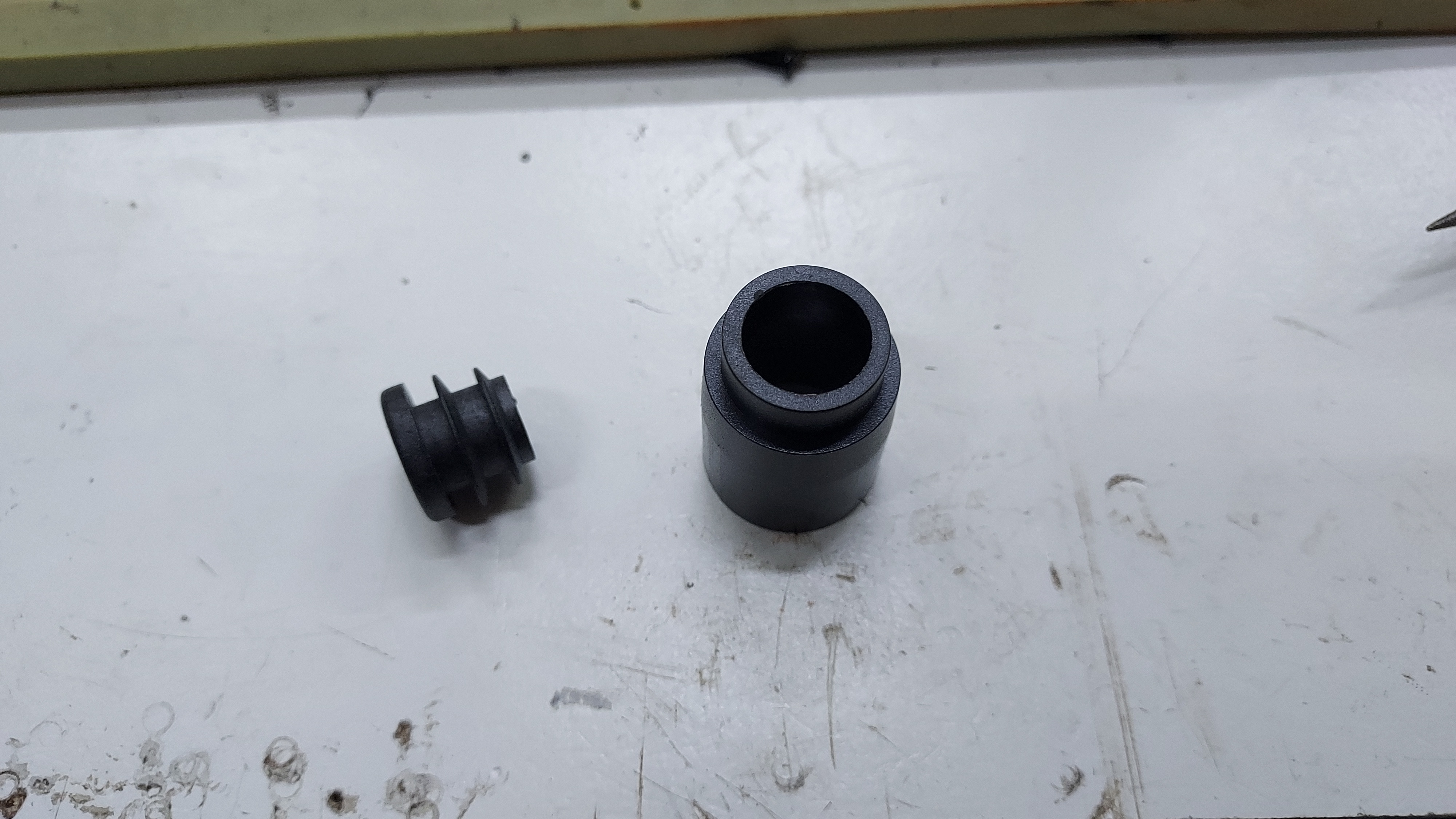
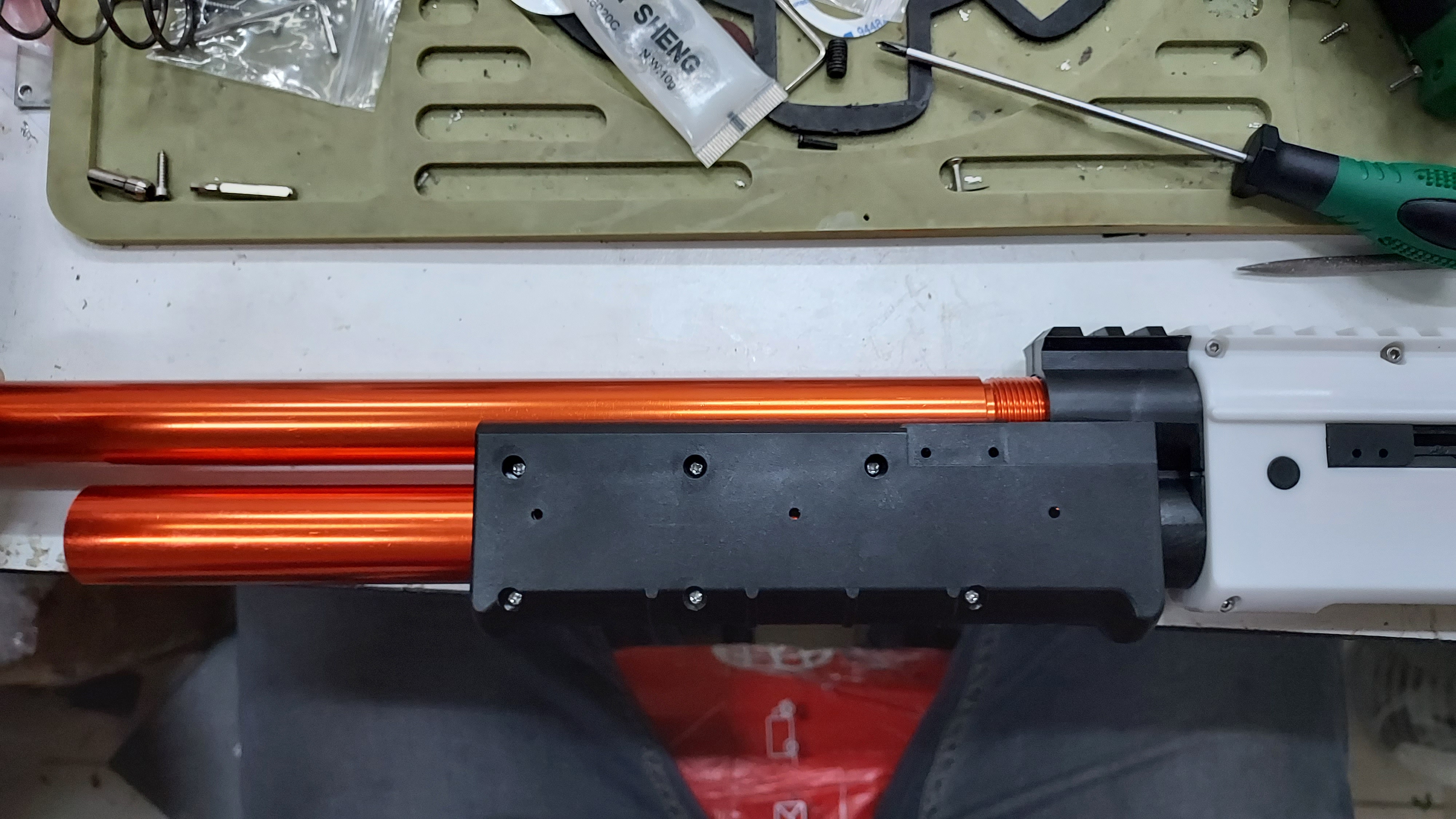
Once the pump grip is built properly, you can place in the main barrel piece now.
Now take the mag tube follower and spring and place it inside the mag tube.
Mag tube spring |
Mag tube follower and spring installed inside the magazine tube. |
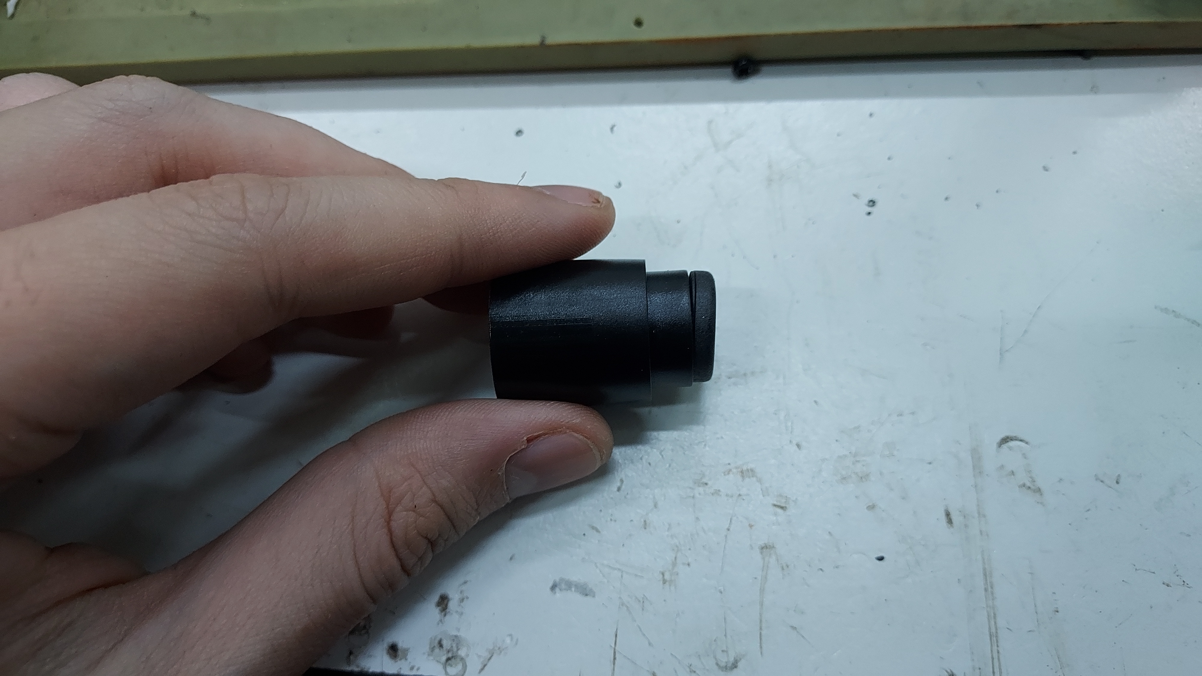
With those parts inside, knock in the mag cap using a mallet.
|
|
You can also use a bit of lubrication on the barrel piece to allow the mag cap to slide in smoother.
.jpg)
Hammer the mag cap all the way in until it looks like the piece in the picture below.
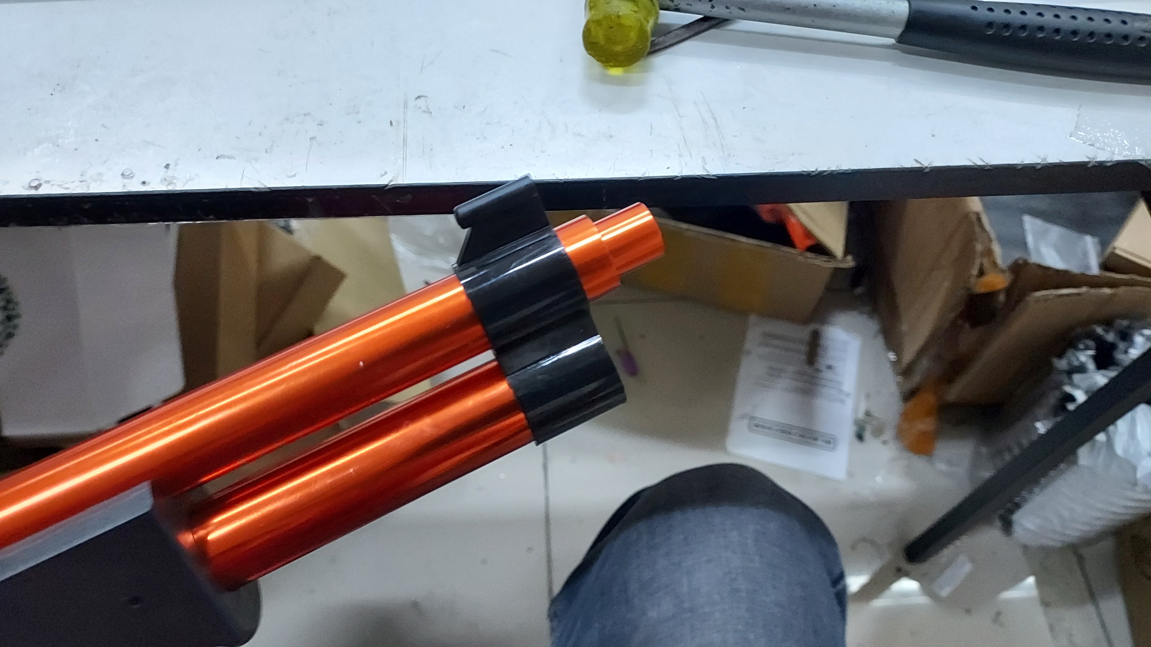
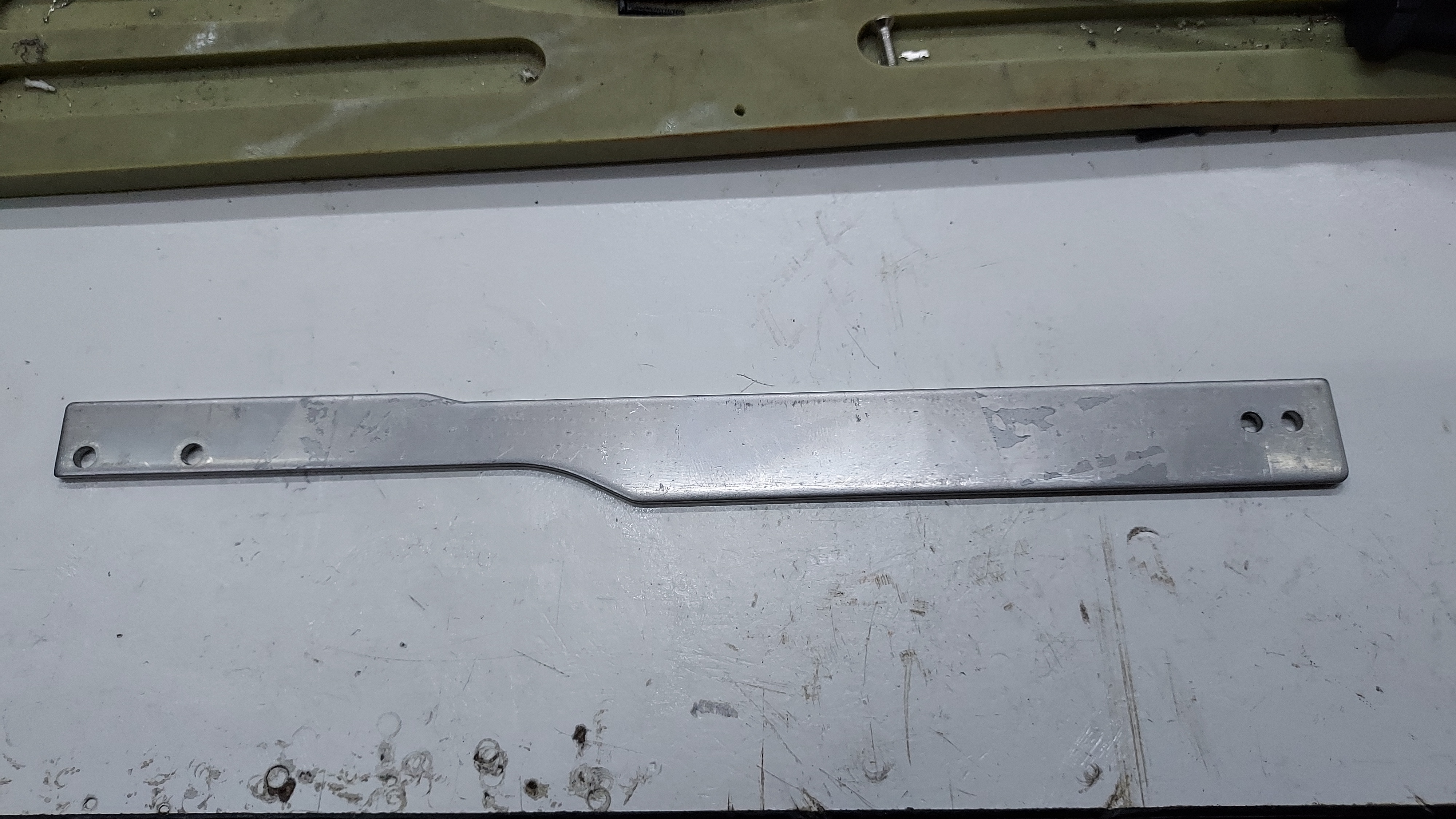
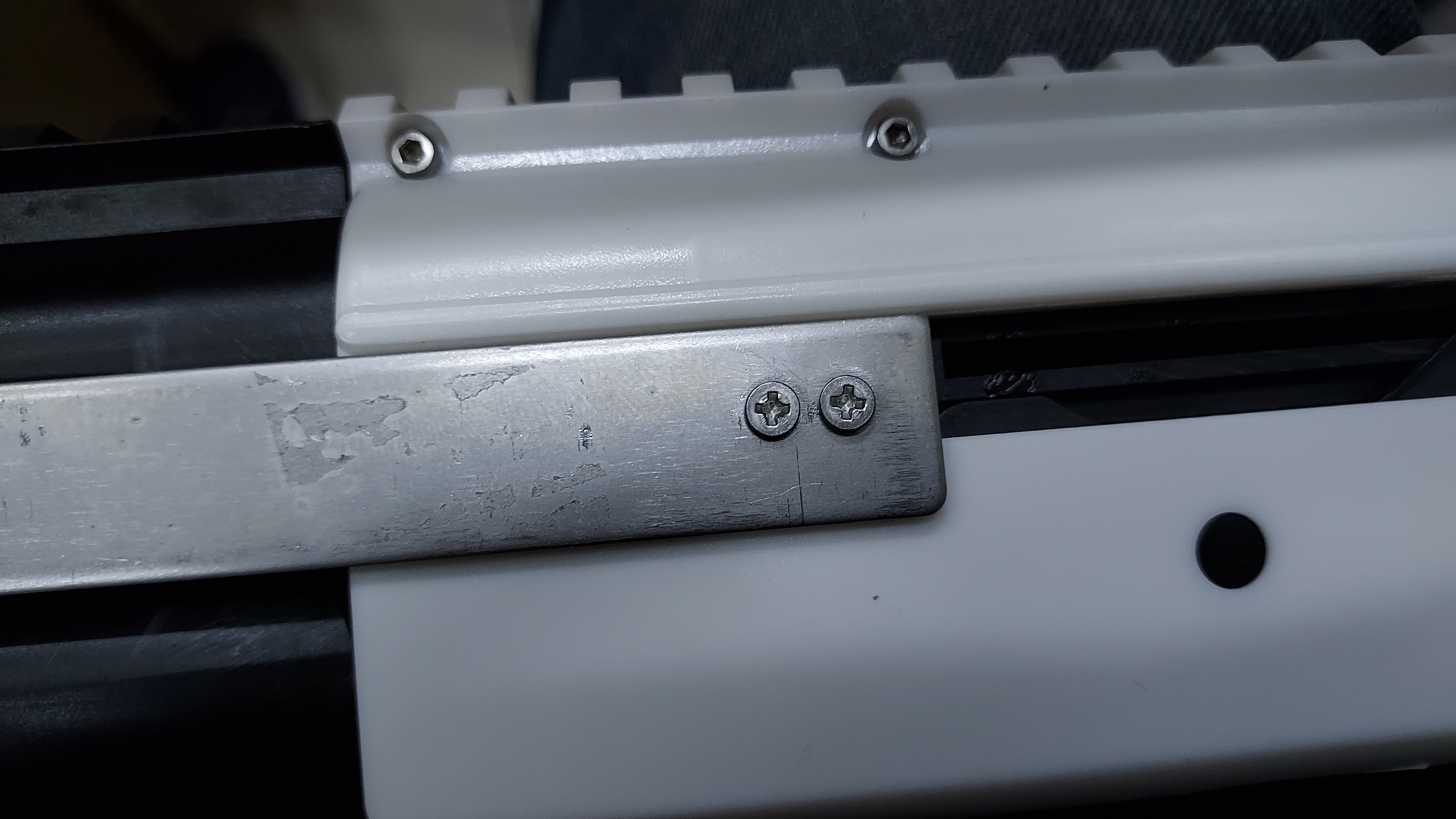
Lastly, place the priming bar on top of the pump grip cut-out and breech of the firefly. Secure the priming bar with
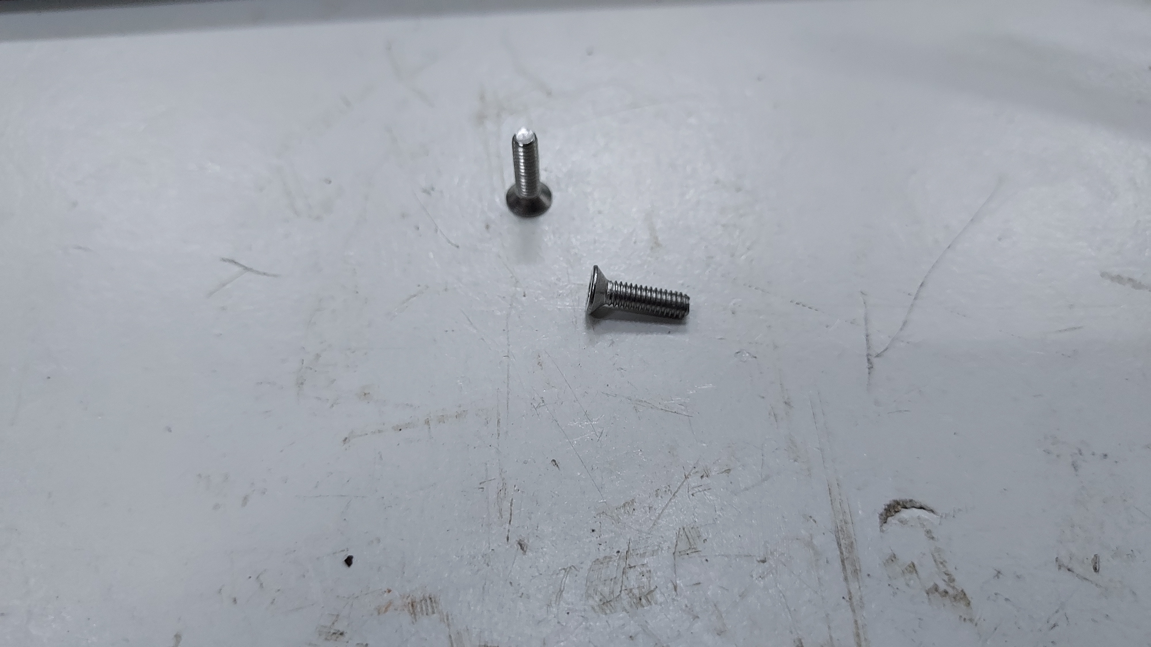
Priming bar and screw piece for priming bar |
Assembled Priming bar |
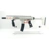
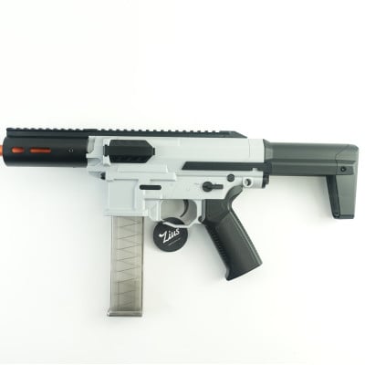
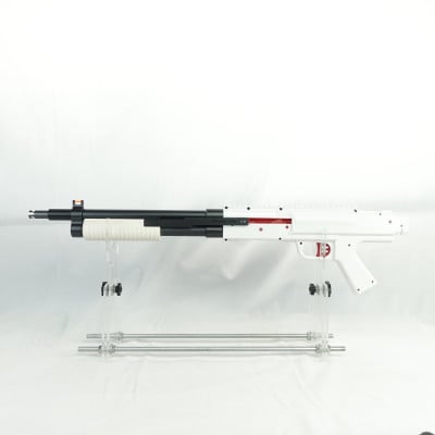
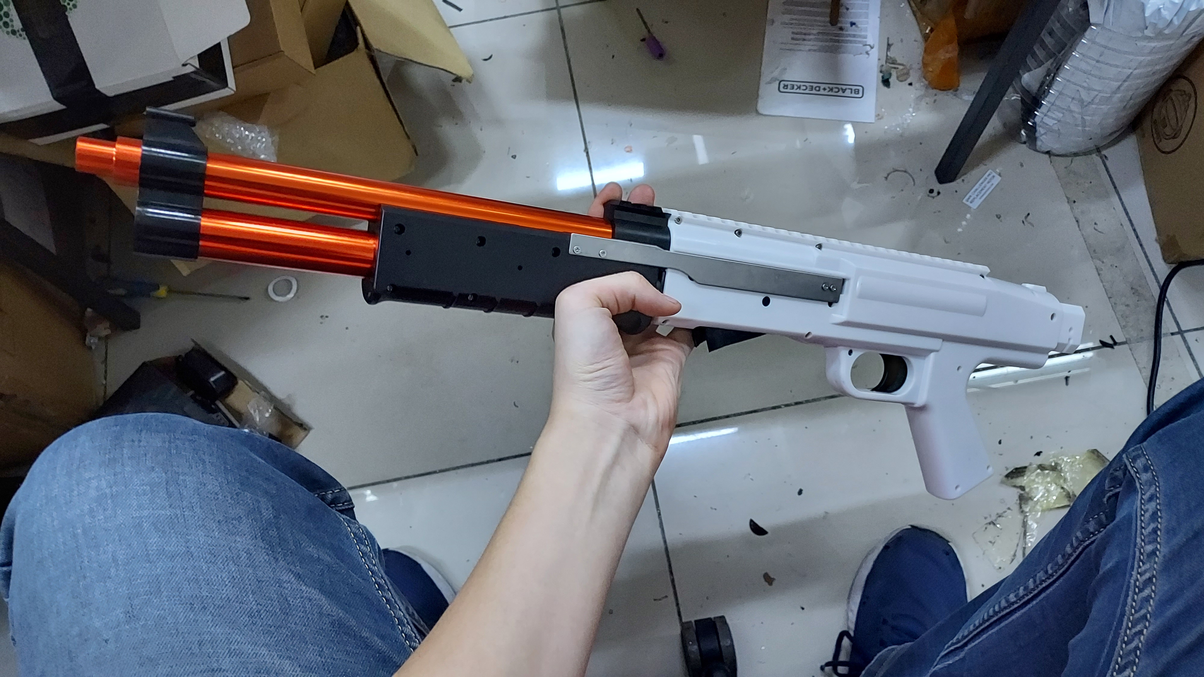
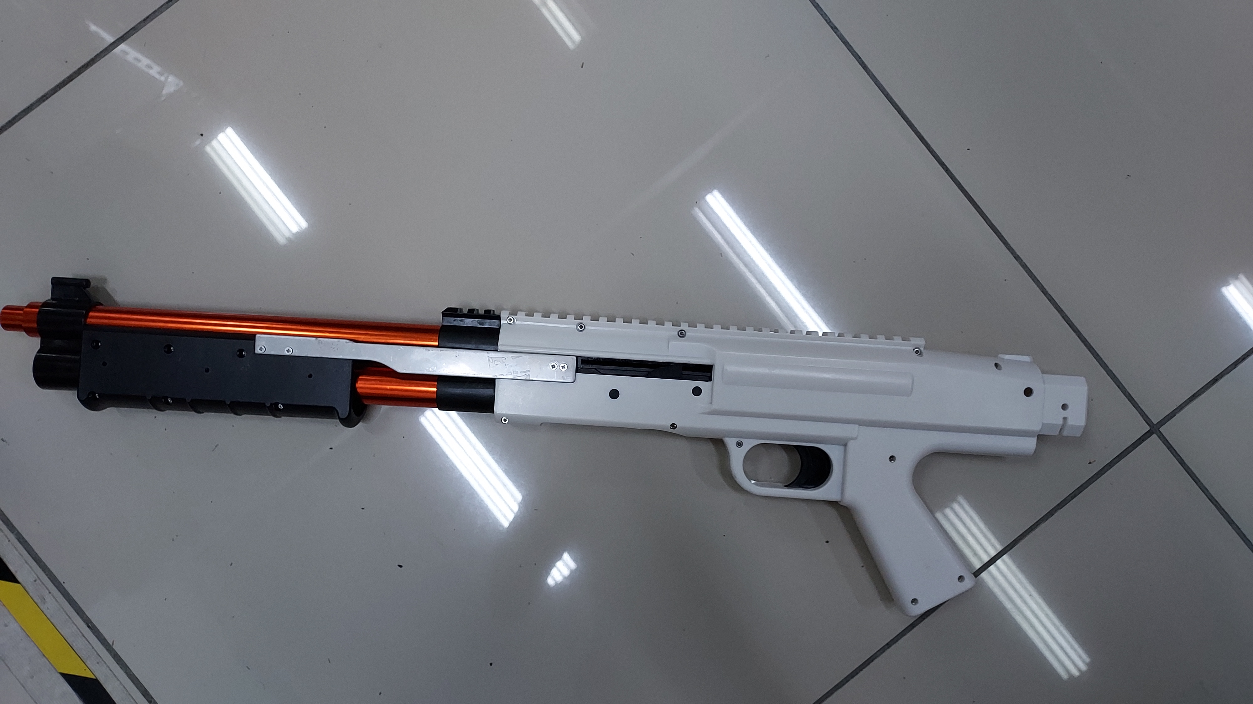
If all of the steps are followed properly, your Firefly blaster will looks like the pictures below.
|
|
Leave a Comment